What are Optical Filters?
Optical filters are devices designed to selectively transmit, reflect, or block specific wavelengths of light. They are widely used in applications such as fluorescence microscopy, Raman spectroscopy, and medical imaging. Typically crafted from glass or plastic, optical filters are often coated with specialized materials to achieve the desired filtering properties.
Absorption Filters vs. Thin Film Interference Filters
Absorption Filters
Absorption filters function by absorbing specific wavelengths of light while allowing others to pass through. Typically made from colored glass or plastic infused with dyes or pigments, these filters block unwanted wavelengths by absorbing them. They are generally cost-effective and suitable for applications where exact wavelength control is not essential. However, absorption filters may fade over time, especially under intense light exposure, and their performance can vary depending on the filter’s thickness.
Examples of absorption filters include colored glass and the dark material used in solar eclipse glasses to block sunlight. In these filters, light energy is absorbed by the material’s atoms, dissipating as heat and effectively eliminating the light. Solar eclipse filters, for example, block all but about one-millionth of visible and ultraviolet light, allowing safe viewing of an eclipse without damaging sensitive eye tissues. Additional examples are colored plastic bottles and traffic signal lights, where only the desired color is visible due to the absorption of other wavelengths.
Thin Film Interference Filters
Thin film interference filters, in contrast to absorption filters, block unwanted colors by reflecting them back toward the source rather than absorbing them. This process relies on optical interference, which exploits the wave properties of light. Each color of light has a specific wavelength, and when multiple light waves interact, they create interference patterns—similar to water waves interacting. Through careful layering of materials with varying refractive indices, these filters are engineered to produce constructive interference for desired wavelengths (which pass through) and destructive interference for undesired wavelengths (which are reflected).
An example of thin film interference is shown in Fig. 1, where a thin film lies on a different material. First, consider light of a wavelength that we want to prevent from passing through the thin film. When this light strikes the top surface of the thin film, part of it reflects back, while some continues through the film, reflects off the second surface, and travels back through the film. When these two rays of light exit the film, they interfere constructively, meaning their amplitudes combine. This constructive interference occurs for all light waves of this particular wavelength, resulting in that wavelength being reflected back toward the source. Consequently, the color associated with this wavelength is “blocked” or “rejected” by the thin film.
In contrast, other wavelengths may undergo destructive interference (as shown in Fig. 2), allowing those colors of light to pass through the thin film with no reflected light.
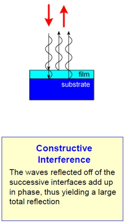
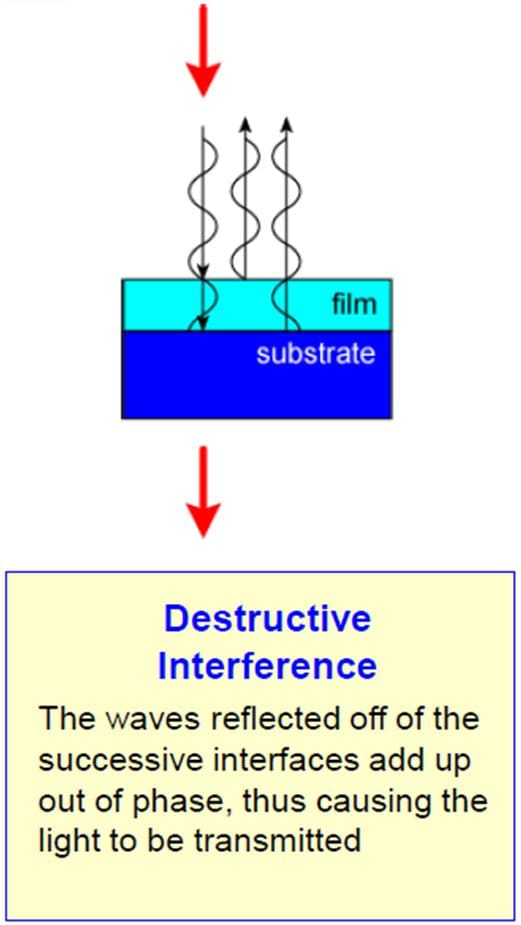
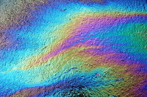
An oil slick on water (Fig. 3) illustrates thin film interference. Looking at the surface of the slick, you can see various colors, indicating that the slick forms a thin film—though not of uniform thickness. The thickness varies by location, causing certain areas to reflect specific colors, such as blue or green, depending on which wavelengths are constructively interfering. Other examples of thin film interference include soap bubbles, which display a spectrum of reflected colors. By shining a light through a soap bubble onto a white sheet of paper, you can also observe the colors that pass through the bubble!
Now that we understand the effects of a single thin film, we can explore what happens with multiple thin films stacked together. Imagine a thin film designed to reflect blue light. As more blue-reflecting films are stacked, the reflection of blue light intensifies.
With a stack of, say, 100 layers, the reflection of blue light becomes so strong that almost no blue light transmits through. For example, only 1 in 1000 parts of the blue light might pass through, with the rest being reflected. This stack is said to block blue light at an optical density (OD) level of 3, where 1 OD unit corresponds to a reduction factor of 10, and OD 3 means a factor of 10³, or 1000.
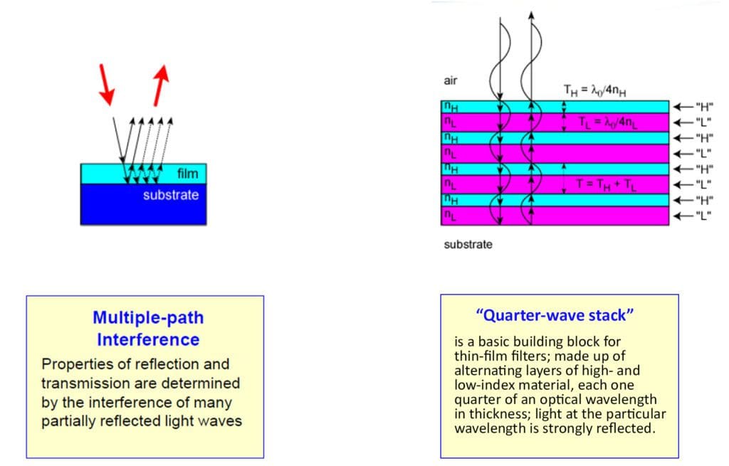
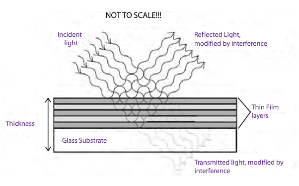
Taking this further, we can stack layers of varying thicknesses to reflect certain colors while transmitting others, creating a bandpass filter that blocks all light except for a specific band of wavelengths. This effect, known as multi-path interference (Fig. 4), results from light interacting with multiple thin-film layers. Unlike an oil slick, which reflects a single color, multi-path interference allows reflection of a broader range of wavelengths, determined by the thickness, number of layers, and materials used in the films.
An example of this concept is shown in Fig. 5, illustrating the “quarter-wave stack.” Varying layer thicknesses, the number of layers, and different materials produce specific optical responses, such as reflection and transmission.
By leveraging multi-path interference theory and applying a comprehensive understanding of the manufacturing process, we design optical filters with “manufacturable specifications.” This ensures that each filter meets its precise specifications, achieves the desired performance, and can be reliably measured to confirm these standards.
Terminology
While general color labels like U (ultraviolet), B (blue), and G (green) are often sufficient for basic filter sets, understanding precise terminology is helpful, especially for specialized filters designed for unique dyes and probes. The most common unit used to describe filter performance is the wavelength of light in nanometers, as with fluorochrome spectra mentioned earlier. The perceived color of a filter depends on both its designated wavelength and its bandwidth (described below). This effect is particularly noticeable for filters in the 550–590 nm range: a narrow-band filter will appear pale green, while a wide-band filter, especially a longpass type, may appear yellowish or even bright orange.
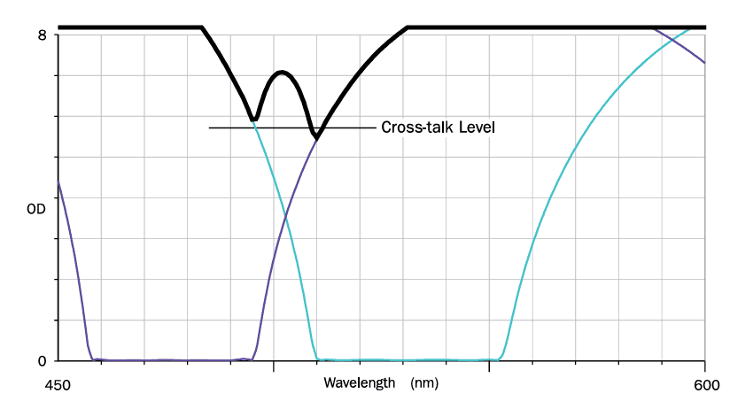
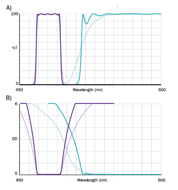
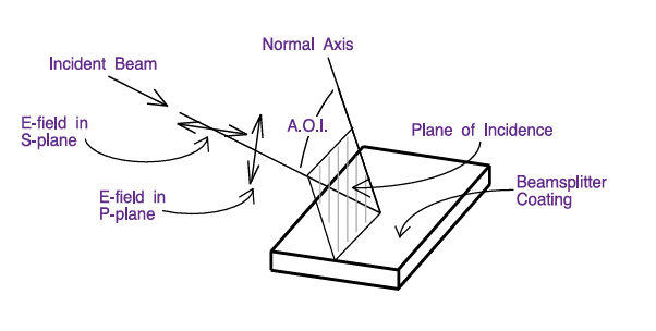
Some key terms used to describe the spectral characteristics of optical filters are defined below. For visual reference, please see Figures 6 through 9.
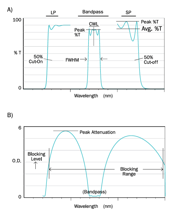
Bandpass Filters: These filters are identified by their center wavelength (CWL) and bandwidth (FWHM). The center wavelength is the average of the wavelengths at 50% of peak transmission, while the FWHM (full width at half maximum) indicates the bandwidth at this 50% transmission level.
Longpass (LP) and Shortpass (SP) Cut-On Filters: LP and SP filters are defined by their cut-on or cut-off wavelengths at 50% of peak transmission. Those with particularly steep slopes are known as edge filters. Average transmission is calculated over the filter’s useful transmission range rather than the entire spectrum. (The terms “highpass” and “lowpass” are less preferred here, as they more accurately apply to frequency rather than wavelength.)
Attenuation Level and Range: The attenuation level (or blocking level) and attenuation range (or blocking range) are typically expressed in optical density (OD) units:
\[\text{OD}=-\log(T)\text{ or }\text{OD}=-\log(\%T/100)\]
Example: \(\text{OD}4.5=3\times10^{-5}T(\text{or }0.003\%T)\)
Optical density, a logarithmic measure similar to absorbance, indicates the extent of attenuation, though filters may block light through mechanisms other than absorption. For instance, thin-film interference filters primarily block by reflection, and acousto-optical filters by diffraction, making “optical density” a more precise term.
Cross-Talk: Related to attenuation, cross-talk (shown in Figure 7) describes the minimum attenuation level when two filters are combined in series. This value is crucial for matching excitation and emission filters in a fluorescence filter set.
Slope: The slope of a filter describes how sharply it transitions from transmission to blocking. Figure 8 compares two sets of filters with identical bandwidths or cut-on points but differing slopes. While the filters may appear similar on a 100% transmission scale, their slopes—shown on the optical density scale—differ significantly. Slope is typically specified by identifying the wavelength where a filter must reach a certain blocking level.
Angle of Incidence (AOI): The AOI is the angle between the optical axis of the incoming light and the axis perpendicular to the filter’s surface, as shown in Figure 9. Most filters are designed for use at zero degrees AOI (normal incidence), though beamsplitter coatings are generally optimized for a 45-degree angle. Many filters, such as thin-film interference coatings and acousto-optical crystal devices, are “angle-sensitive,” meaning their performance characteristics vary with angle. If a filter or beamsplitter is to be used at an angle other than the standard zero or 45 degrees, this must be explicitly specified.
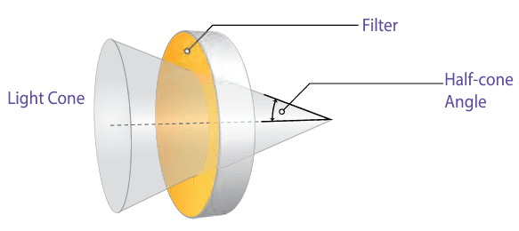
A consequence of angle sensitivity is that the half-cone angle of the incident light may need to be specified when using a filter in a converging or diverging beam (see Figure 10). This half-cone angle can also be expressed in terms of the f-number or the numerical aperture (NA) of the light beam, where the NA equals the sine of the half-cone angle.
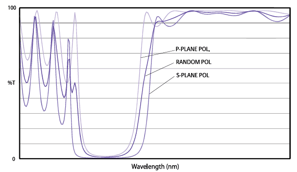
Dichroic Beamsplitters and Polarization: Dichroic beamsplitters—and any thin-film interference coatings used at non-normal angles of incidence—introduce a degree of polarization, with the effect varying significantly based on wavelength and coating design. Relevant terms are shown in Figure 9:
P-plane (also called TM-mode, or transverse magnetic) refers to the component of the electric field vibration parallel to the plane of incidence on the beamsplitter.
S-plane (or TE-mode, transverse electric) refers to the component perpendicular to the plane of incidence.
The polarizing effect of a typical dichroic beamsplitter is illustrated in Figure 11, highlighting how different components of the electric field are influenced by the coating.
Available Products
The primary filter technologies used in fluorescence analysis are colored filter glass and thin-film coatings, with acousto-optical tunable filters also gaining popularity in specialized applications. Other products, such as holographic filters and liquid-crystal tunable filters, exist but are less frequently used in fluorescence microscopy.
Colored Filter Glass
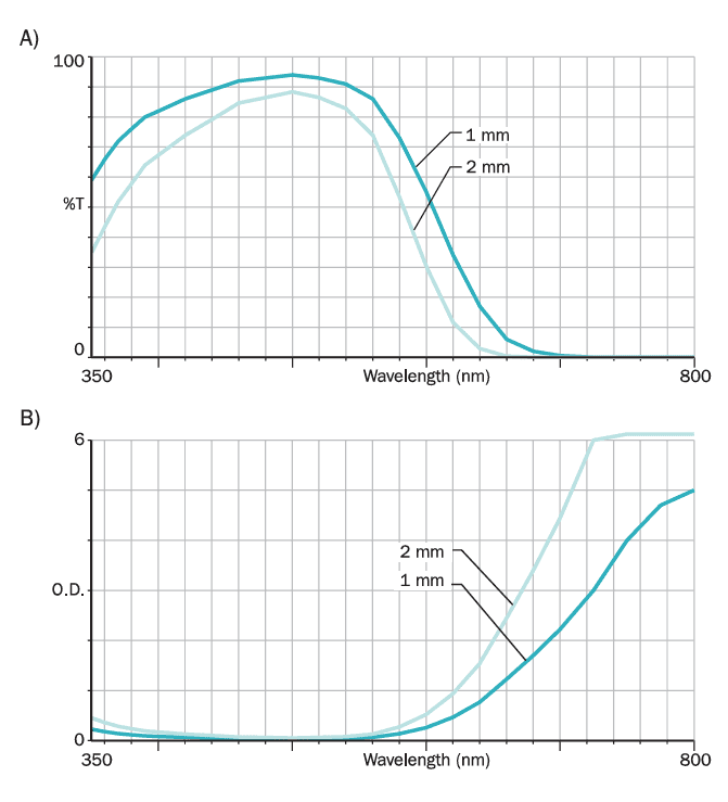
Colored filter glass, also known as absorption glass, is the most commonly used filter in fluorescence analysis. This includes yellow and orange sharp-cut glasses and “black” glasses that transmit UV while absorbing visible light. Filter glass works by attenuating light solely through absorption, meaning its spectral performance depends on the glass’s physical thickness. Increasing the thickness enhances the blocking level but also reduces the peak in-band transmission (see Figure 12), so an optimal thickness must be determined. The stock thicknesses offered by glass manufacturers are typical for general applications, but other thicknesses may be more suitable for specific uses.
Advantages of Filter Glass
- It is relatively inexpensive.
- It is stable and durable under normal conditions spectral characteristics remain consistent regardless of the angle of incidence, aside from minor changes due to increased effective thickness.
Disadvantages of Filter Glass
- There is a limited selection of available glass types.
- Bandpass filters often exhibit poor slope and low peak transmittance.
- The dependence of spectral performance on thickness reduces flexibility in specifying filter thickness.
- Many longpass filter glasses have high autofluorescence.
- Intense illumination can cause untempered filter glass to crack, as absorption converts much of the radiant energy into heat.
Included in the filter glass category are polymer-based filters, sometimes used as longpass barrier filters due to their lower autofluorescence compared to equivalent glass filters. This category also includes a type of neutral-density glass (distinct from thin-film neutral-density coatings discussed below).
Thin-Film Coatings
Thin-film coatings come in two widely used types:
- Metallic Coatings: These are used to create fully reflective mirrors and neutral-density filters.
- Thin-Film Interference Coatings: These are the primary component of interference filters and offer significant performance flexibility.
The main advantage of thin-film interference coatings is their design flexibility, based on their method of operation. As shown in Figure 13, interference coatings consist of stacks of ultra-thin material layers, each with a thickness close to a light wavelength (often about a quarter-wavelength or roughly 1/10,000 of a millimeter). Although each layer is colorless, the reflections at each layer interface combine through wave interference to selectively reflect certain wavelengths while transmitting others. A natural example of thin-film interference is seen in the colorful swirls on a soap bubble, where interference occurs between reflections from the inner and outer surfaces, with colors following areas of constant thickness within the single soap layer.
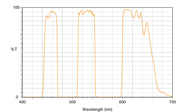
Interference coatings can create almost any filter type, including bandpass, shortpass, longpass filters, and dichroic beamsplitters. By varying the number of layers in the stack and the thickness of each, the filter’s nominal wavelength, bandwidth, and blocking level can be precisely controlled. Complex filters beyond simple bandpass, longpass, or shortpass designs are also achievable. For instance, multi-band filters created using modified magnetron sputter deposition (see Figure 14) can yield several highly transmissive bands, making them essential in applications like fluorescence microscopy.
Limitations of Thin-Film Interference Coatings
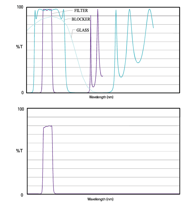
- Finite Blocking Range: In traditional interference filter designs, blocking performance is limited to a specific wavelength range. This longstanding coating technology uses dielectric materials in a sealed, laminated format. To extend the blocking range, additional interference coatings or absorption glass can be added, but this increases physical thickness and can reduce transmission. Figure 15 compares an “unblocked” filter to one with added blocking components. Such filters are effective in applications like fixed cell stains, plant imaging with autofluorescence, flow cytometry, and plate readers, where signals are robust enough.Recent coating advances, however, have mitigated some of these limitations. High-energy coating technologies now extend blocking ranges while maintaining transmission. Filters produced using modified magnetron sputtering, for instance, achieve broader blocking ranges through sophisticated design strategies with minimal impact on bandpass transmission. This enhanced signal-to-noise ratio supports high-quality data acquisition in photon-critical applications.
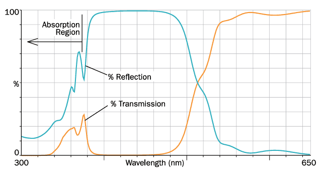
- Material Transparency Limits: Traditional filter materials are limited by their transparency range; outside of this range, they tend to absorb light instead of transmitting or reflecting it. Materials optimized for visible filters, for instance, often absorb heavily in the UV, necessitating alternative materials that may lack ideal properties. Consequently, UV filters often have limited performance and design flexibility, and it’s not always possible to infer reflectivity from a transmission spectrum based on zero absorption assumptions. Figure 16 shows a dichroic beamsplitter designed for high reflectivity in the visible range; in the UV, transmission drops due to absorption, not reflection. High-energy coating technology now enables the use of materials with extended transparency into the violet and near-UV ranges.
- Angle Sensitivity and Polarization: Thin-film interference coatings are sensitive to the angle of incidence (AOI); as the angle increases, the coating’s spectral characteristics shift to shorter, “blue-shifted” wavelengths. Additionally, coatings at oblique angles introduce unwanted polarization effects in most applications. While designers can reduce this polarization effect, it cannot be entirely eliminated. However, in certain specialized applications, this polarization sensitivity is used advantageously.
Acousto-Optical Tunable Filters (AOTF)
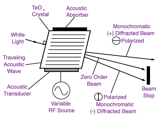
The acousto-optical tunable filter (AOTF), illustrated schematically in Figure 17, is commonly used for filtering laser excitation light. It operates by setting up radio-frequency acoustic vibrations in a crystal, creating a bulk transmission diffraction grating. By adjusting the frequency, the AOTF can rapidly tune to diffract specific wavelengths of light within its range with high precision. Typically, an AOTF can accept incident light with a maximum half-cone angle of about 5 degrees. Controlled electronically via an external unit, the AOTF offers several advantages:
- Fast Wavelength Tuning: The AOTF can switch to any wavelength within microseconds, perform wavelength scanning, and enable multi-band filtering by combining multiple radio frequencies.
- Intensity Modulation: It allows rapid variation in intensity by adjusting the amplitude of acoustic vibrations.
However, the AOTF has some limitations:
- Limited FWHM (Full Width at Half Maximum): Around 2 nm in the visible range, restricting light output from white light sources when used as an excitation filter.
- Physical Constraints: It has a small aperture (approximately 10 mm or less) and a large overall thickness (about 25 mm).
- Linearly Polarized Output: The output is linearly polarized, achieving a maximum transmission of 50% when using unpolarized incident light.
Liquid Crystal Tunable Filters (LCTF)
The liquid crystal tunable filter (LCTF) is an electronically controlled device increasingly used as an emission filter due to its imaging-quality filtering, ample clear aperture, and in-line optical path. The LCTF consists of multiple waveplates, each formed by a birefringent layer paired with a liquid crystal layer and sandwiched between linear polarizers. The birefringence of the liquid crystal layer, and thus the overall effect of the waveplate, is adjusted by changing the voltage applied to transparent conductive coatings next to the liquid crystal layer.
The birefringence in the waveplate induces a wavelength-dependent rotation of incoming polarized light, which is then attenuated to varying degrees by the second polarizer. This attenuation, based on the light’s rotation, effectively converts the rotation into amplitude variation that is also wavelength-dependent. The LCTF’s filtering parameters can be tailored by adjusting aspects such as the number of waveplates and the birefringence properties of each waveplate.
Characteristics of LCTFs:
- Fast Wavelength Selection: Switching speed is on the order of milliseconds.
- No Image-Shift: Wavelength changes don’t affect image alignment.
- Variable Attenuation: The device allows for different attenuation levels.
- Customizable Bandwidth and Spectral Range: Offers options for FWHM, tunability range, and blocking level, though these parameters are somewhat interdependent.
LCTFs are polarizing components, so the maximum transmission for unpolarized light is approximately 50%. Real-world transmission may be lower, depending on wavelength and blocking level. However, using specialized polarizing beamsplitters in an epi-fluorescence microscope can reduce the impact of these transmission losses. The highest commercially available blocking level for LCTFs is around \(10^{−5}\).
