Designing antireflection coatings at high angles of incidence is considerably more complex compared to coatings designed for normal incidence. Simplifications occur when considering only one plane of polarization. In this case, the process involves converting the admittances into tilted or modified optical admittances at the appropriate angle of incidence. These values are then used to design coatings in a manner similar to normal incidence.
The primary complication arises because the range of available admittances differs significantly from the range at normal incidence. In particular, for s-polarization, the available range is less favorable.
We will first briefly examine antireflection coatings for one polarization and subsequently discuss designs involving both polarizations, where the challenge lies in managing completely different sets of admittances for each polarization.
For simplicity in this discussion, we will assume an angle of incidence of 60° in air, with the following parameters:
– Substrate refractive index: 1.5
– Possible film indices: 1.3, 1.4, 1.5, …, 2.5
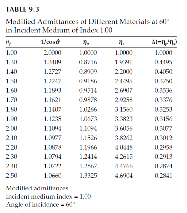
In practice, real designs will depend on available indices, resulting in additional constraints and potentially requiring more layers. The modified admittances for various indices and polarization conditions, characterized by values of \(\Delta = \frac{\eta_p}{\eta_s}\), are summarized in Table 9.3.
1. p-Polarization Only
At an incidence angle of 60°, the modified p-admittance of the substrate is 0.9186, which corresponds to a single-surface reflectance for p-polarized light of less than 0.2%—an acceptable level for most applications.
It is worth noting that this angle is only slightly greater than the Brewster angle. If an even lower reflectance is desired, a single quarter-wave layer with admittance given by:
\[
\eta = \sqrt{0.9186 \times 1.0000} = 0.9584
\]
is required. From Table 9.3, this admittance corresponds to a refractive index just over 1.6, which is greater than the substrate’s refractive index of 1.5.
Behavior at Higher Angles of Incidence
As the angle of incidence increases beyond 60°, the required index for the quarter-wave layer also increases. Eventually, at very high angles of incidence, the required layer index exceeds the highest available film index. At this point, designs involving multiple layers, such as Air | HL | Glass, become necessary. Here:
– H represents a high-index layer.
– L represents a low-index layer.
These layers must be quarter-wave thicknesses, adjusted for the specific angle of incidence. However, such designs have two major drawbacks:
1. Narrow angular range: These coatings operate efficiently only over a very small range of angles of incidence.
2. Production difficulty: Achieving the required layer accuracy is extremely challenging.
If at all possible, it is preferable to avoid these high-incidence designs altogether by redesigning the optical system to minimize the angle of incidence. This approach simplifies the coating design and avoids the complications associated with high-index requirements and precision manufacturing.
2. s-Polarization Only
For s-polarized light, the modified s-admittance for the substrate is 2.449, and the required single-layer admittance for perfect antireflection is:
\[
\eta = \sqrt{2.4495 \times 1.0000} = 1.5650
\]
This value is well below the available range of film indices. The problem here is similar to that encountered at normal incidence, where materials with sufficiently low refractive indices are unavailable.
Solution
The approach to solving this involves raising the admittance of the substrate to an acceptable level by first adding a quarter-wave layer with a higher admittance.
1. A convenient choice is a layer with an index of 1.9 (admittance: 3.3823).
2. This raises the resultant admittance to:
\[
\eta = \frac{(3.3823)^2}{2.449} = 4.6713
\]
3. To complete the design, a second quarter-wave layer is added with an admittance given by:
\[
\eta = \sqrt{4.6713 \times 1.0000} = 2.1613
\]
This value corresponds closely to a refractive index of 1.4 (admittance: 2.2000).
Performance and Reflectance
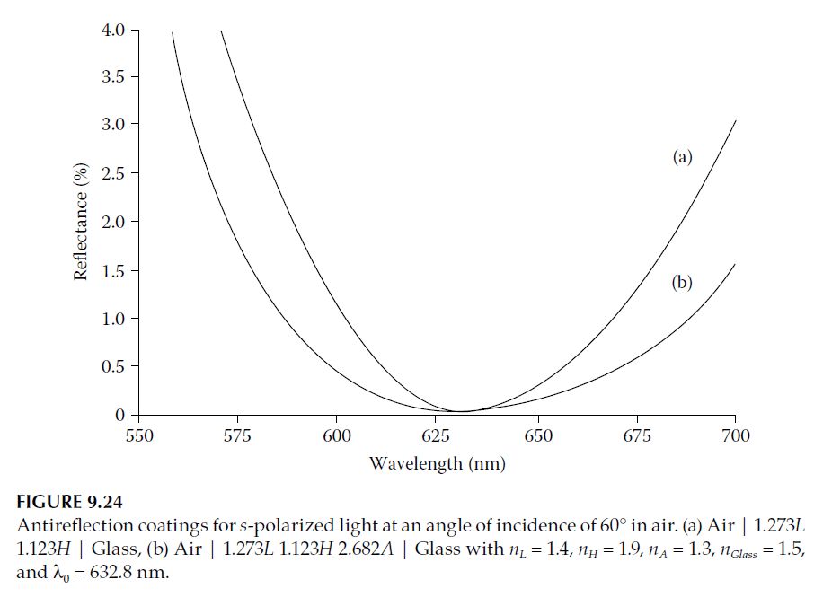
Using this two-layer design, the residual reflectance is reduced to 0.03%, a significant improvement over the 17.7% reflectance of the uncoated substrate. However, this design does not have a broad angular or spectral performance, as confirmed by Figure 9.24.
Further Optimization
A small improvement can be achieved by inserting a high-admittance half-wave layer between the two quarter-wave layers, or alternatively, adding a low-admittance half-wave layer next to the substrate. The two designs, in terms of normal-incidence quarter-wave thicknesses, are as follows:
1. Design 1:
\[
\text{Air | 1.273L 1.123H | Glass}
\]
– L: Low-index quarter-wave layer (index 1.4)
– H: High-index quarter-wave layer (index 1.9)
2. Design 2:
\[
\text{Air | 1.273L 1.123H 2.682A | Glass}
\]
– L: Low-index quarter-wave layer (index 1.4)
– H: High-index quarter-wave layer (index 1.9)
– A: Low-admittance quarter-wave layer (index 1.3)
Polarization Limitations
It is important to note that the p-reflectance of these designs is very high, making them suitable only for s-polarized light.
Design Recommendation
Wherever possible, it is preferable to avoid the need for such complex antireflection coatings. A better approach is to rearrange the optical design of the instrument so that s-polarized light is reflected, while p-polarized light is transmitted. This simplifies the design and improves overall optical performance.
3. s- and p-Polarization Together
Achieving low reflectance for both s- and p-polarized light is extremely challenging and should be attempted only as a last and costly resort. It is possible to design coatings effective over a narrow wavelength range, and one such approach is presented here.
We use the indices provided in Table 9.3 to design a coating that minimizes reflectance for both polarizations on a substrate with a refractive index of 1.5 in air. The design uses quarter-wave layer thicknesses and follows a procedure similar to high-reflectance coatings. However, an additional condition is imposed: the admittance of both the substrate and coating for both polarizations must equal unity to match the incident medium.
Design Conditions
The conditions for equal reflectance and zero reflectance are as follows:
\[
\Delta_1^2 / \Delta_2^2 / \Delta_3^2 \dots \Delta_{sub} = 1 \tag{9.39}
\]
\[
\eta_{s1}^2 / \eta_{s2}^2 / \eta_{s3}^2 \dots \eta_{sub} = 1 \tag{9.40}
\]
– Equation (9.39): Ensures the p-reflectance equals the s-reflectance.
– Equation (9.40): Ensures the s-reflectance (and therefore the p-reflectance) is zero.
Starting Values
From Table 9.3, the starting values are:
– \(\Delta_{sub} = 0.3750\)
– \(\eta_{sub} = 2.4495\)
By trial and error, it is found that adding a single quarter-wave layer with a refractive index of 1.3 gives the best result. This corresponds to:
\[
\Delta_1^2 / \Delta_{sub} = \frac{0.4495^2}{0.3750} = 0.5387
\]
\[
\eta_{1s}^2 / \eta_{sub} = \frac{1.9391^2}{2.4495} = 1.5350
\]
Other combinations provide values farther from unity. Adopting the quarter-wave layer (n = 1.3) as the first layer, an additional correction factor is required:
– Δ correction: \(1.3624\)
– \(\eta_s\) correction: \(0.8071\)
A single layer cannot satisfy both corrections. However, a two-layer combination of a high-index layer followed by a low-index layer comes close to the requirements for Δ but is insufficient for \(\eta_s\).
Two-Layer Design
The nearest two-layer combination involves a high-index layer (n = 1.8) followed by a low-index layer (n = 1.3). This results in:
\[
\Delta = \frac{(0.4495^2 \times 0.4495^2)}{(0.3253^2 \times 0.3750)} = 1.0288
\]
\[
\eta_s = \frac{(1.9391^2 \times 0.9391^2)}{(3.1560^2 \times 2.4495)} = 0.5795
\]
However, an alternative two-layer combination of n = 2.5 followed by n = 1.4 gives a similar Δ correction but a different \(\eta_s\) correction. Combining both approaches in a four-layer design allows adjustment of \(\eta_s\) without altering Δ.
Four-Layer Design
The correction factors are as follows:
\[
\Delta = \frac{(0.4495^2 \times 0.2841^2)}{(0.4050^2 \times 0.3253^2)} = 0.9396
\]
\[
\eta_s = \frac{(1.9391^2 \times 4.6904^2)}{(2.2000^2 \times 3.1560^2)} = 1.7159
\]
Combining these results:
\[
\Delta_{\text{final}} = 0.9396 \times 1.0288 = 0.9667
\]
\[
\eta_{s, \text{final}} = 1.7159 \times 0.5795 = 0.9944
\]
The seven-layer design can be arranged in various orders without affecting reflectance at the reference wavelength, as long as the 1.3 and 2.5 indices are odd and the 1.4 and 1.8 indices are even. The final design is:
\[
\text{Air | 1.3409L 1.2727A 1.3409L 1.1407B 1.3409L 1.1407B 1.066H | Glass}
\]
where:
– \(n_L = 1.30\)
– \(n_A = 1.40\)
– \(n_B = 1.80\)
– \(n_H = 2.50\)
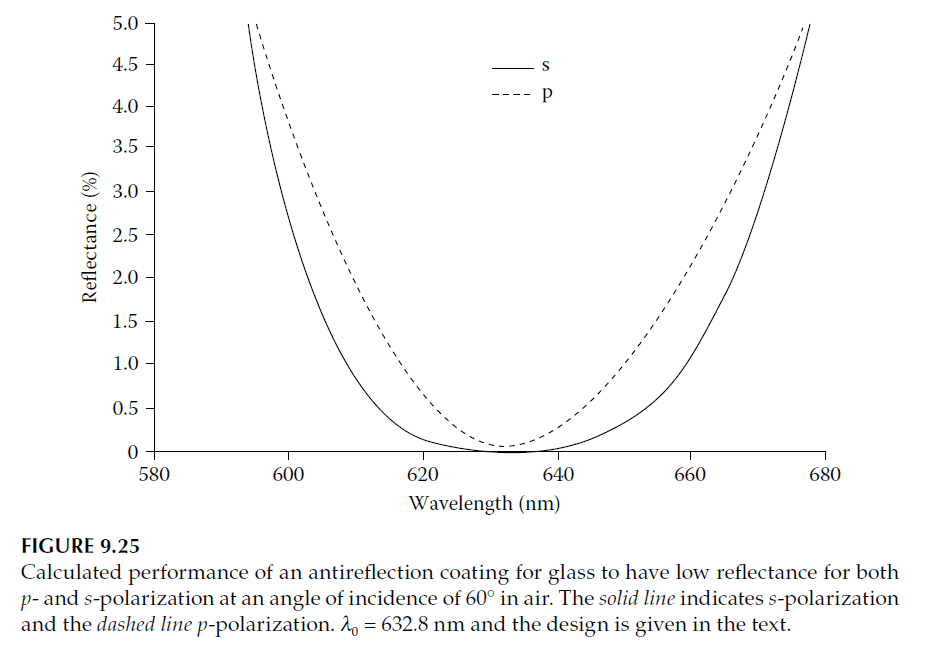
The calculated performance for a reference wavelength of 632.8 nm is shown in Figure 9.25.
Alternative Design
For a substrate with an index of 1.52 and film indices ranging from 1.35 to 2.40, a 10-layer design can be used:
\[
\text{Air | 1.3036L 1.1748A 1.3036L 1.1748A 1.3036L 1.1407B 1.0722H 1.1235C 1.0722H 1.1235C | Glass}
\]
where:
– \(n_L = 1.35\), \(n_A = 1.65\), \(n_B = 1.80\), \(n_C = 1.90\), \(n_H = 2.40\)
– \(n_{\text{Glass}} = 1.52\), \(n_{\text{Air}} = 1.00\)
The performance is similar to Figure 9.25.
Conclusion
The designs presented illustrate the advantage of using more than two materials for coatings that address both polarizations. The increased flexibility comes at a cost: such coatings are highly sensitive to the precise values of refractive index, especially at oblique incidence.
The ideal antireflection coating remains the inhomogeneous layer discussed in previous tutorials. It acts as an effective antireflection coating as long as its total phase thickness exceeds half a wavelength. When tilted, the profile changes slightly, but the antireflection properties are maintained as long as the angle of incidence remains below the point where the phase thickness becomes less than half a wavelength.
However, the challenge of finding materials with sufficiently low refractive indices for the outermost parts of an inhomogeneous layer persists at oblique incidence.