Although the theory developed for antireflection coatings on high-index materials applies equally well to low-index materials, the problem becomes much more challenging due to the lack of rugged thin-film materials with very low refractive indices. Magnesium fluoride, with a refractive index of approximately 1.38, represents the lowest practical index currently achievable. This limitation makes the manufacture of designs derived from the straightforward application of the techniques discussed so far largely impractical.
Challenges in Low-Index Antireflection Coating Design
Design techniques for antireflection coatings on low-index materials are less formalized and involve considerably more intuition and trial and error compared to those for high-index materials. A very common low-index substrate is crown glass, with coatings often required for the visible spectrum, which spans wavelengths from around 400 nm to 700 nm. Plastic materials with similar or higher refractive indices are also becoming increasingly prevalent, especially in applications such as spectacle lenses.
Practical Considerations for Coating Low-Index Materials
For most coatings discussed here, we assume a substrate refractive index of 1.52, typical for crown glass, though this value may vary slightly depending on the specific glass type and wavelength. Although the techniques are primarily applied to antireflection coatings for crown glass, they are equally relevant to other low-index materials.
Starting Point: The Single-Layer Coating
To establish a foundation, we begin by examining the simplest possible antireflection coating—a single-layer coating. Subsequent sections will expand on this foundation, introducing multi-layer designs and advanced techniques tailored to the specific challenges posed by low-index substrates.
1. The Single-Layer Antireflection Coating
We can make use of the expressions already developed for high-index materials. The optimum single-layer coating is a quarter-wave optical thickness for the central wavelength ( \lambda_0 ), with optical admittance given by:
\[
y_1 = \sqrt{y_0 y_m} \tag{4.14}
\]
For crown glass in air, this represents:
\[
y_1 = \sqrt{1.0 \times 1.52} = 1.23
\]
As already mentioned, the lowest practical film index currently available is that of magnesium fluoride, around 1.38 at 500 nm. While not ideal, this provides a worthwhile improvement. The reflectance at the minimum is given by:
\[
R = \left( \frac{y_m – y_0}{y_m + y_0} \right)^2 \tag{4.15}
\]
This yields a reflectance of approximately 1.3% per surface.
At angles of incidence other than normal, the phase thickness of the layer is reduced, so for a given layer thickness, the wavelength corresponding to the minimum becomes shorter. The optical admittance appropriate to the angle of incidence and the plane of polarization should also be used to calculate the reflectance. Figure 4.18 shows how the reflectance of a single layer of magnesium fluoride on a substrate of index 1.52 varies with the angle of incidence.
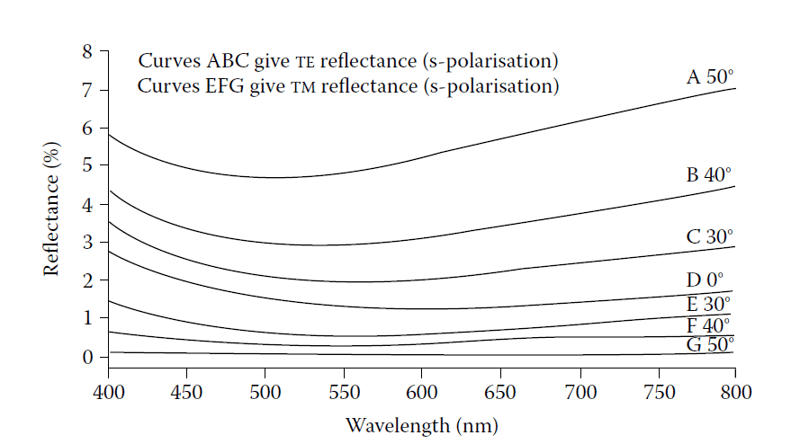
The computed reflectance at various angles of incidence of a single surface of glass of index
1.52 coated with a single layer of magnesium fluoride of index 1.38 and optical thickness at
normal incidence one quarter-wave at 600 nm.
2. Two-Layer Antireflection Coatings
The single-layer coating cannot achieve zero reflectance, even at the minimum, due to the lack of suitable low-index materials. A thin layer of high-index material placed next to the substrate can make the substrate appear to have a higher index, enabling a subsequent layer of magnesium fluoride to be more effective.
Schuster Diagram for Two-Layer Coatings
We can study the Schuster diagram (Figure 4.8) for coatings on glass with an index of 1.52, reproduced here as Figure 4.19.
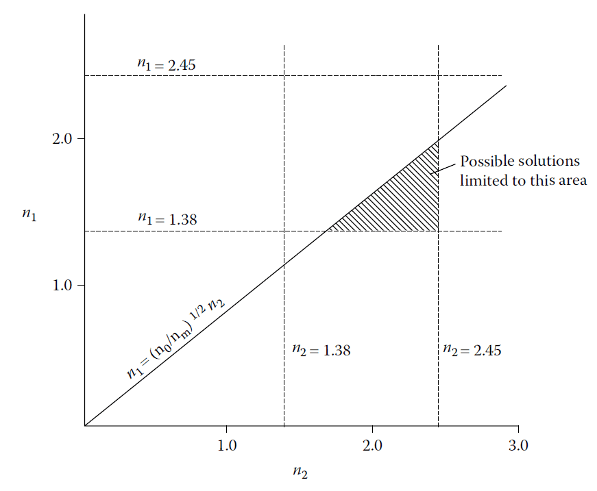
A Schuster diagram for two-layer coatings on glass (n = 1.52) in air (n = 1.0). Possible layer indices
are assumed to be limited to the range 1.38–2.45.
Assuming 1.38 as the lowest possible index and 2.45 as a realistic upper bound for high-index materials, solutions are limited to the shaded area of the diagram. This area is bounded by the lines:
\[
y_1 = 1.38, \quad y_2 = 2.45, \quad y_1 y_2 = \sqrt{y_0 y_m}
\]
Solutions along the line \( y_1 y_2 = \sqrt{y_0 y_m} \) consist of two quarter-wave layers. Other solutions involve two layers of unequal thickness—one greater and the other less than a quarter-wave. The thicknesses are given by:
\[
\tan^2 \delta_1 = \frac{(y_m – y_2)(y_2 – y_0)}{(y_m – y_0)y_2}, \quad \tan^2 \delta_2 = \frac{(y_m – y_1)(y_1 – y_0)}{(y_m – y_0)y_1} \tag{4.16}
\]
Example Coating
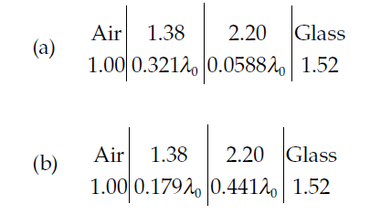
Consider a high-index layer with \( y_2 = 2.2 \) (e.g., cerium oxide) and a low-index layer with \( y_1 = 1.38 \) (e.g., magnesium fluoride). The two possible solutions are:
\[
\delta_1 = 0.3208 \, \pi, \, \delta_2 = 0.05877 \, \pi \quad \text{and} \quad \delta_1 = 0.1792 \, \pi, \, \delta_2 = 0.4412 \, \pi
\]
These solutions are plotted in Figure 4.20. The characteristic is a single minimum, with the broader solution associated with the thinner high-index layer.
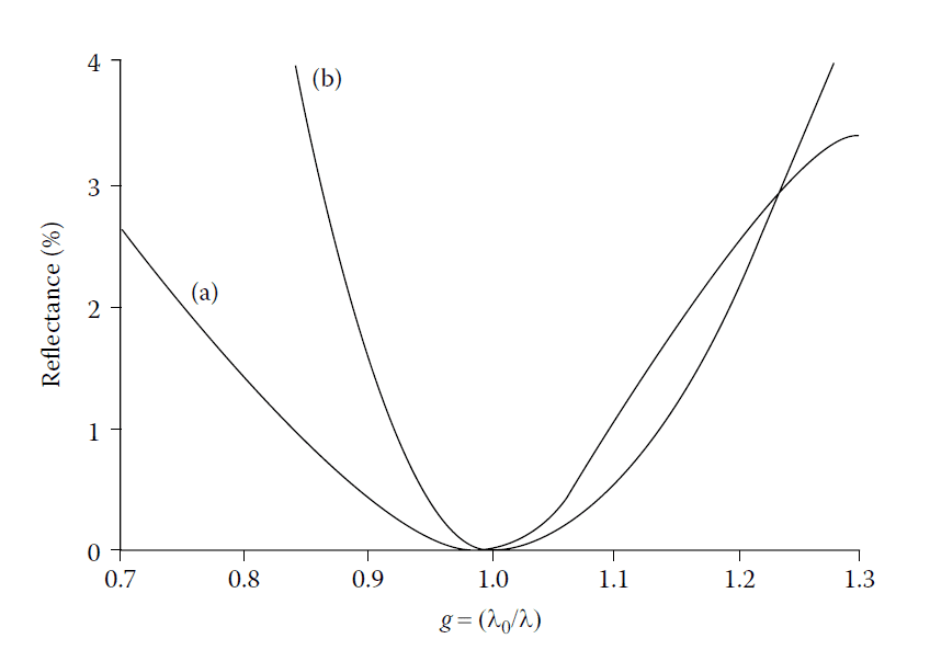
Two-layer antireflection coatings for glass. (a), the broader characteristic, is usually selected. Because of the characteristic single minimum
the coating is often known as a V-coat.
Variation with Substrate Index
As the substrate index increases, the high-index layer becomes thinner, broadening the characteristic of the coating. Figure 4.21 shows how the values of \( \delta_1 \) and \( \delta_2 \) vary with the index of the layer next to the substrate, revealing good performance stability.
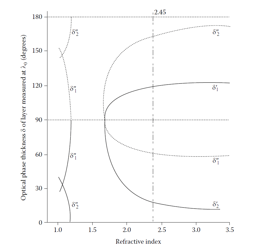
Optimum thicknesses of the layers in a double-layer antireflection coating at normal incidence.
δ\(_1\) and δ\(_2\), the optical phase thicknesses given by Equations 4.7 and 4.8, are plotted
against n\(_2\), the refractive index of the high-index layer. The low-index layer is assumed to be
magnesium fluoride of index 1.38 and the coating is deposited onto glass of index 1.50. Two
pairs of solutions of Equations 4.7 and 4.8 are possible for each set of refractive indices and are
denoted by δ\(_1\)’ and δ\(_2\)’ and δ\(_1\)’’ and δ\(_2\)’’. The value, 2.45, of refractive index, shown by the broken
line, corresponds to bismuth oxide and was used by Catalan in his calculations.
Angular Performance
Catalan computed reflectance values for a two-layer coating of bismuth oxide \(( n = 2.45 )\) and magnesium fluoride \(( n = 1.38 )\) on glass \(( n = 1.5 )\) at various angles of incidence. Figures 4.22 and 4.23 show the performance, which is excellent up to 20°, but declines at higher angles.
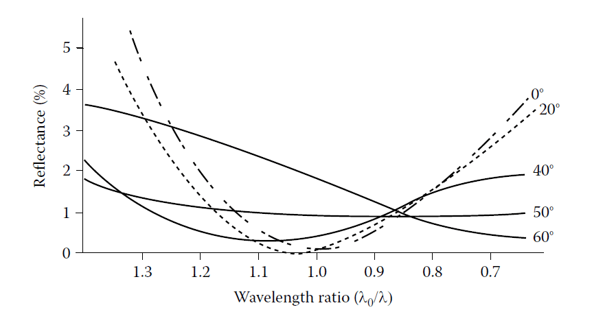
Theoretical p-reflectance (TM) as a function of wavelength ratio g (= λ\(_0\)/λ) of a double-layer
antireflection coating. n\(_0\) = 1.00, n\(_1\) = 1.38, n\(_2\) = 2.45, n\(_m\) = 1.50.

Theoretical s-reflectance (TE) as a function of wavelength ratio g (=λ\(_0\)/λ) of a double-layer antireflection
coating. n\(_0\) = 1.00, n\(_1\) = 1.38, n\(_2\) = 2.45, n\(_m\) = 1.50.
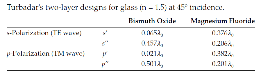
For coatings designed for non-normal incidence, Turbadar published solutions for 45° incidence using the same materials. These designs, summarized in Table 4.1, show performance curves under various conditions, including error effects. Figure 4.24 shows equireflectance contours plotted over a grid of angle of incidence against wavelength.
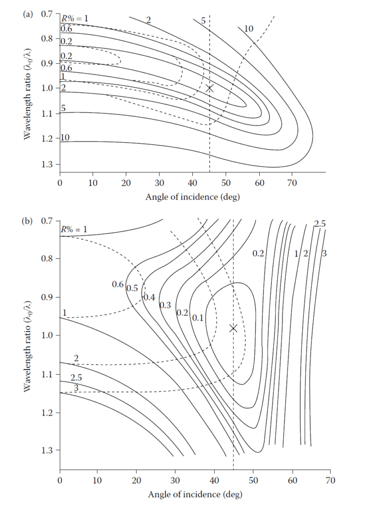
(a) Equireflectance contours for double-layer antireflection coatings on glass. n\(_0\) = 1.00, n\(_1\) = 1.38,
n\(_2\) = 2.45, n\(_m\) =1.50, with layer thicknesses optimized for polarization (TE) at 45° angle of incidence,
given by S’ in Table 4.1. Solid curves, s-reflectance (TE); broken curves, p-reflectance
(TM). (b) Equireflectance contours for
double-layer antireflection coatings on glass. n\(_0\) = 1.00, n\(_1\) = 1.38, n\(_2\) = 2.45, n\(_m\) = 1.50, with layer
thicknesses optimized for polarization (TM) at 45° angle of incidence, given by P’ in Table 4.1.
Solid curves, p-reflectance (TM); broken curves, s-reflectance (TE).
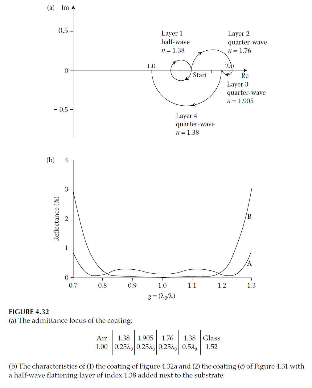
Admittance Plot for Two-Layer Coatings
An admittance plot helps visualize performance. It consists of two circles:
- Low-Index Layer \(( y_1 )\): Passes through \( (y_0, 0) \) and \( \left(\frac{y_1^2}{y_0}, 0\right) \).
- High-Index Layer \(( y_2 )\): Passes through \( (y_m, 0) \) and \( \left(\frac{y_2^2}{y_m}, 0\right) \).
If these circles intersect, a two-layer coating is feasible. Figure 4.25 illustrates this, showing two possible arrangements.
Admittance diagram showing the two possible double-layer antireflection coating designs.
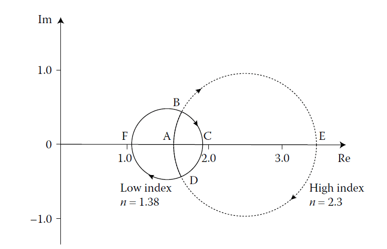
Quarter-Wave Case
When \( y_1 y_2 = \sqrt{y_0 y_m} \), the circles touch internally, corresponding to two quarter-wave layers. The theoretical performance curve is shown in Figure 4.26.
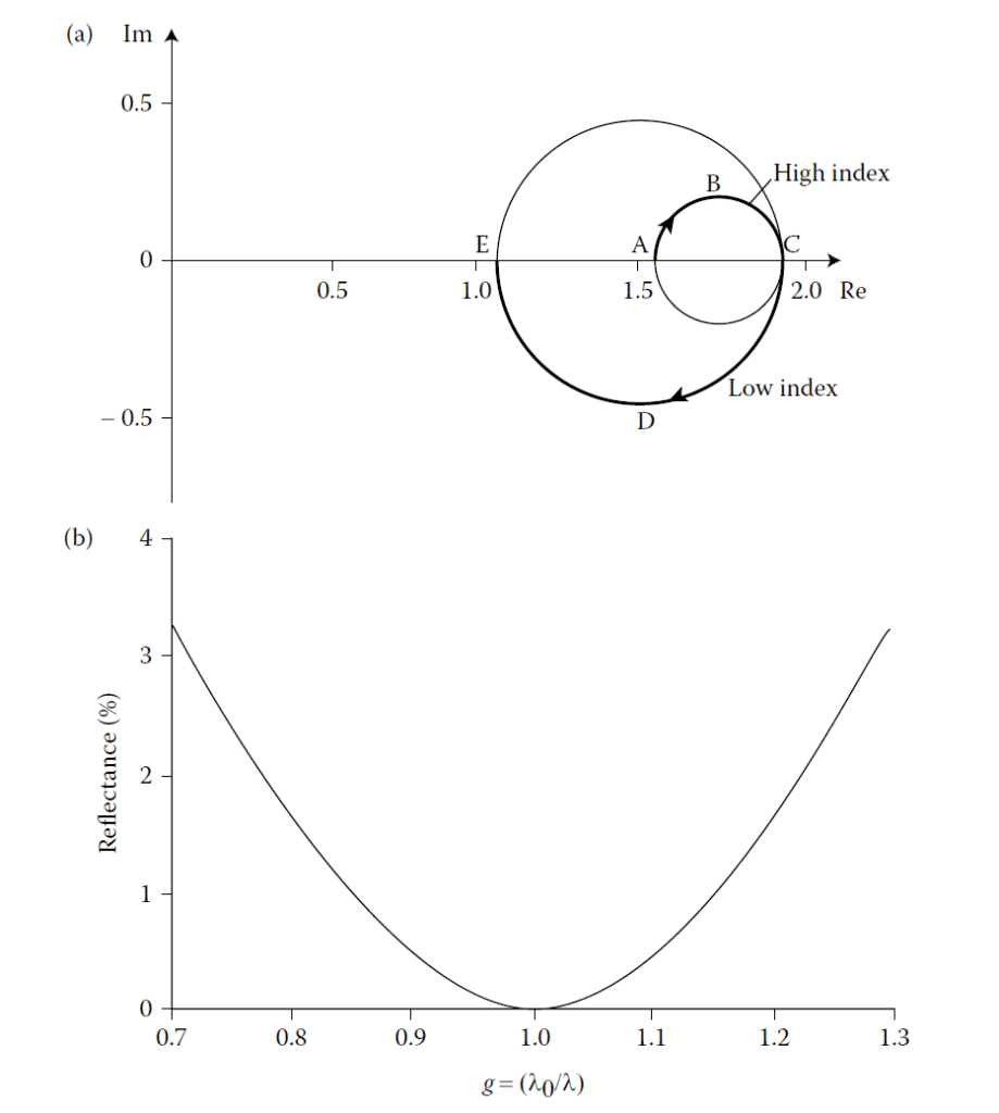
Special case of the two-layer antireflection coating where the layers become quarter-waves and
the two solutions of Figure 4.25 merge into one. (a) The admittance locus. (b) The theoretical performance curve. The design is
Half-Wave Improvement
A half-wave layer of high index between the substrate and the quarter-wave low-index film improves performance by broadening the spectrum. Figure 4.27 illustrates this effect in an admittance plot.
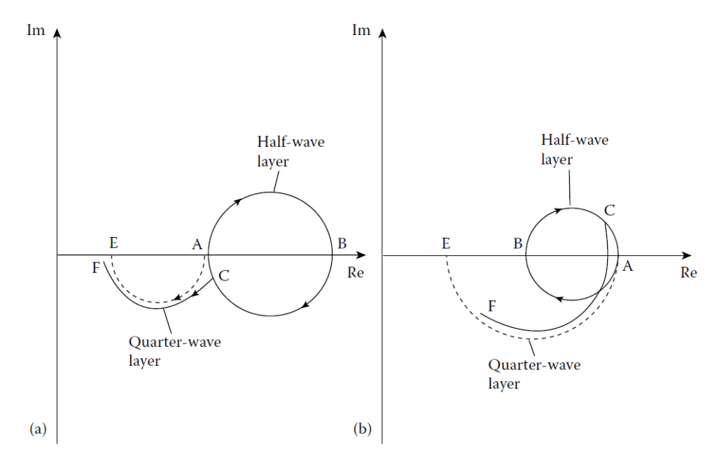
The operation of a half-wave flattening layer. The contour AE represents a low-index quarterwave
coating and, in ABA, a half-wave layer is inserted between it and the substrate. In (a),
the half-wave is of index higher than the substrate, and as g (= λ0/λ) varies, the action of the
half-wave keeps the end of the quarter-wave near the point E and the reflectance remains low.
ABCF represents the locus with g somewhat less than unity. g greater than unity would give
a similar effect with the point C now above the real axis and the loci slightly longer than full
circle and semicircle. (b) shows the corresponding diagram for a low-index half-wave. Here
the end point is dragged rapidly away from E as g varies and the reflectance rises rapidly.
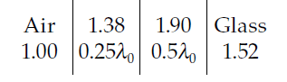
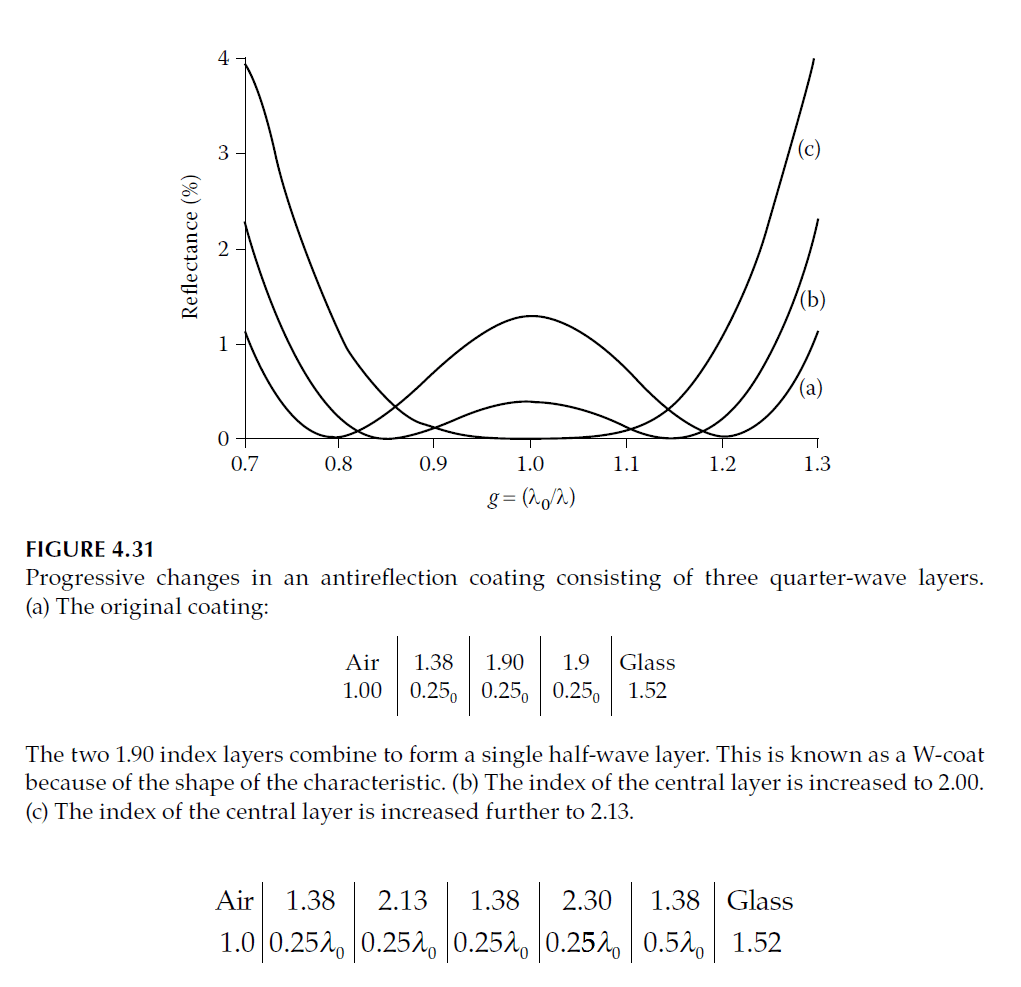
Flattening is therefore effective in (a) but not in (b). Note that the reflectance curve for another
coating with half-wave flattening layer of design is shown as curve (a) of Figure 4.31. This latter coating is sometimes called a W-coat because of
the shape of the characteristic.
3. Multilayer Antireflection Coatings
To achieve higher performance than two-layer coatings allow, multilayer coatings are necessary. These coatings address the limitations in usable film indices and enable broader spectral ranges of low reflectance.
Thetford’s Three-Layer Design Technique
Thetford devised a method for designing three-layer antireflection coatings with zero reflectance at two wavelengths and low reflectance over a wider range compared to two-layer designs. The structure includes:
- A layer of intermediate index next to the substrate.
- A high-index layer.
- A low-index outer layer.
The indices are predetermined, and the method calculates the necessary thicknesses. This approach has the advantage of specifying indices rather than thicknesses, making it practical given the limited availability of materials.
Key Principles of Thetford’s Technique
- Amplitude and Phase Conditions: The coating is split into two subsystems on either side of a middle spacer layer. Transmittance is maximized if:
- The reflectances of the two subsystems are equal.
- The phase thickness \( \delta \) of the middle layer satisfies:
\[
\phi + \phi’ – 2\delta = 2s\pi, \quad s = 0, \pm1, \pm2, \dots \tag{4.17}
\]
Here, \( \phi \) and \( \phi’ \) are the phases of the reflection coefficients at the boundaries of the middle layer.
- Trial-and-Error Optimization: Thetford used vector diagrams and approximations to adjust the layer thicknesses iteratively until the desired performance was achieved.
Design Process
The design is based on vector and Smith’s methods, as shown in Figure 4.28:
- Initial Setup: Vectors \( \rho \) and \( \rho’ \) are equal in length at a reference wavelength \( \lambda_0 \) (Figure 4.28d).
- Second Solution: A shorter wavelength \( \lambda_1 \) is determined where \( \rho \) and \( \rho’ \) remain equal (Figure 4.28e). The required changes in reflectance \( \Delta\rho^2 \) are calculated:
\[
\Delta\rho^2 = -4\rho_a\rho_b \sin\delta_1 \Delta\delta_1
\]
\[
\Delta\rho’^2 = -4\rho_c\rho_d \sin\delta_3 \Delta\delta_3
\]
Phase conditions for \( \delta_2 \), the middle layer, are then checked.
Key Results
- Broad Reflectance Region: If the phase condition is satisfied at both \( \lambda_0 \) and \( \lambda_1 \), the reflectance remains low across a broad region.
- Effect of Middle Layer Index: Figure 4.29 illustrates how performance improves as the middle layer’s index changes.

Figure 4.28
Thetford’s method for antireflection coating design. (a) The three-layer coating split into two sections, I and II, on either side of the central high-index
layer. (b) The vector diagram of section I. (c) The vector diagram of section II. (d) The vector diagrams of sections I and II superimposed, showing one
possible orientation of ρ and ρ’ so that they are of equal length. (e) An alternative orientation of ρ and ρ’ where again they are of equal length. The
arrangement in (d) is also shown. The vectors ρa, ρb, ρc, and ρd have been omitted. (f) The two possible orientations of φ’ from (d) and (e). Also shown,
(g), is the mirror image of ρ0 in the horizontal axis.

Figure 4.29
Calculated reflectance of some three-layer antireflection coatings designed by Thetford. The
designs are as follows:
(a). n\(_0\) = 1.00, n\(_1\) = 1.38, n\(_2\) = 2.00, n\(_3\) = 1.80, n\(_4\) = n\(_m\) = 1.52, n\(_1\)d\(_1\) = 0.205λ\(_0\), n\(_2\)d\(_2\) = 0.336λ\(_0\),
n\(_3\)d\(_3\) = 0.132λ\(_0\).
(b). n\(_0\) = 1.00, n\(_1\) = 1.38, n\(_2\) = 2.10, n\(_3\) = 1.80, n\(_4\) = n\(_m\) = 1.52, n\(_1\)d\(_1\) = 0.225λ\(_0\), n\(_2\)d\(_2\) = 0.359λ\(_0\),
n\(_3\)d\(_3\) = 0.152λ\(_0\).
(c). n\(_0\) = 1.00, n\(_1\) = 1.38, n\(_2\) = 2.20, n\(_3\) = 1.80, n\(_4\) = n\(_m\) = 1.52, n\(_1\)d\(_1\) = 0.227λ\(_0\), n\(_2\)d\(_2\) = 0.338λ\(_0\),
n\(_3\)d\(_3\) = 0.170λ\(_0\).
(d). n\(_0\) = 1.00, n\(_1\) = 1.38, n\(_2\) = 2.40, n\(_3\) = 1.80, n\(_4\) = n\(_m\) = 1.52, n\(_1\)d\(_1\) = 0.247λ\(_0\), n\(_2\)d\(_2\) = 0.445λ\(_0\),
n\(_3\)d\(_3\) = 0.181λ\(_0\).
Analytical Considerations
The design is effective when the admittance diagram remains close to the ideal form shown in Figure 4.28. If necessary, additional layers can refine the design to enhance performance further.
Four-Layer Designs
For applications requiring only two refractive indices, four-layer coatings can achieve similar performance to three-layer designs. In such designs:
- High and low-index layers alternate.
- The high-index layer nearest the air replaces the intermediate index layer of three-layer designs.
- Refinements (e.g., splitting layers into quarter-wave sections) improve performance (Figure 4.30).

Figure 4.30
Calculated reflectance of four-layer antireflection coatings on glass showing the performance
before and after the design was refined by computer. The two designs are:
(a). Before refining: n\(_0\) = 1.00, n\(_1\) = n\(_3\) = 1.38, n\(_2\) = n\(_4\) = 2.10, n\(_3\) = 1.80, n\(_5\) = n\(_m\) = 1.52, n\(_1\)d\(_1\) = 0.21λ\(_0\),
n\(_2\)d\(_2\) = 0.37λ\(_0\), n\(_3\)d\(_3\) = 0.036λ\(_0\), n\(_4\)d\(_4\) = 0.070λ\(_0\).
(b). After refining: n\(_0\) = 1.00, n\(_1\) = n\(_3\) = 1.38, n\(_2\) = n\(_4\) = 2.10, n\(_3\) = 1.80, n\(_5\) = n\(_m\) = 1.52, n\(_1\)d\(_1\) = 0.216λ\(_0\),
n\(_2\)d\(_2\) = 0.458λ\(_0\), n\(_3\)d\(_3\) = 0.072λ\(_0\), n\(_4\)d\(_4\) = 0.049λ\(_0\).
Additional Design Examples
Quarter-Half-Quarter Coating
A quarter-half-quarter coating consists of:
- A quarter-wave low-index outer layer.
- A half-wave high-index middle layer.
- A quarter-wave low-index layer near the substrate.
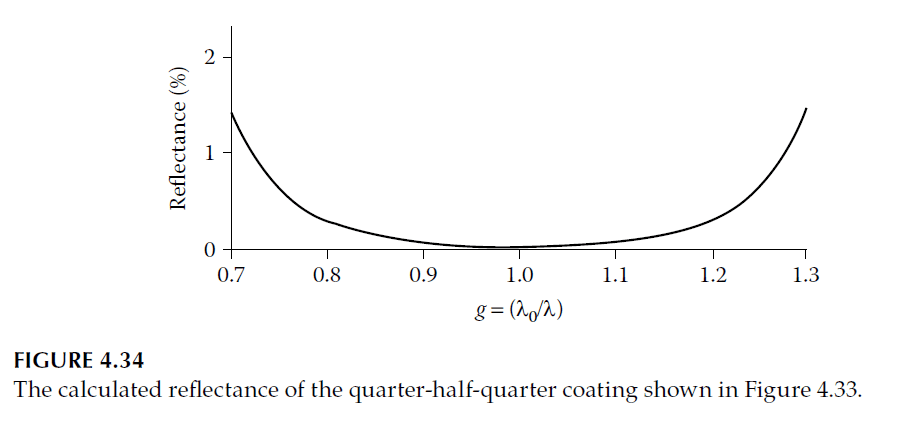
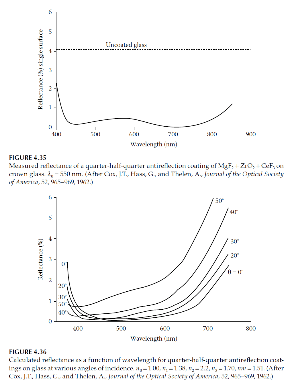
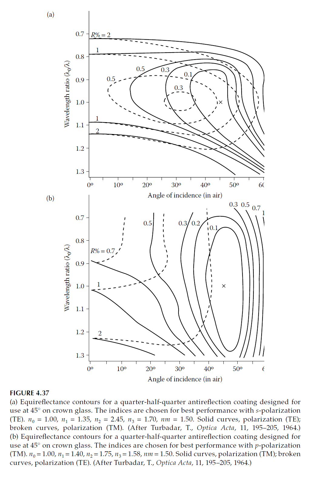
The admittance plot (Figure 4.33) shows broadening due to the high-index half-wave layer. Practical coatings with indices in the range 2.0–2.4 demonstrate good results (Figure 4.34).
Multilayer Extensions
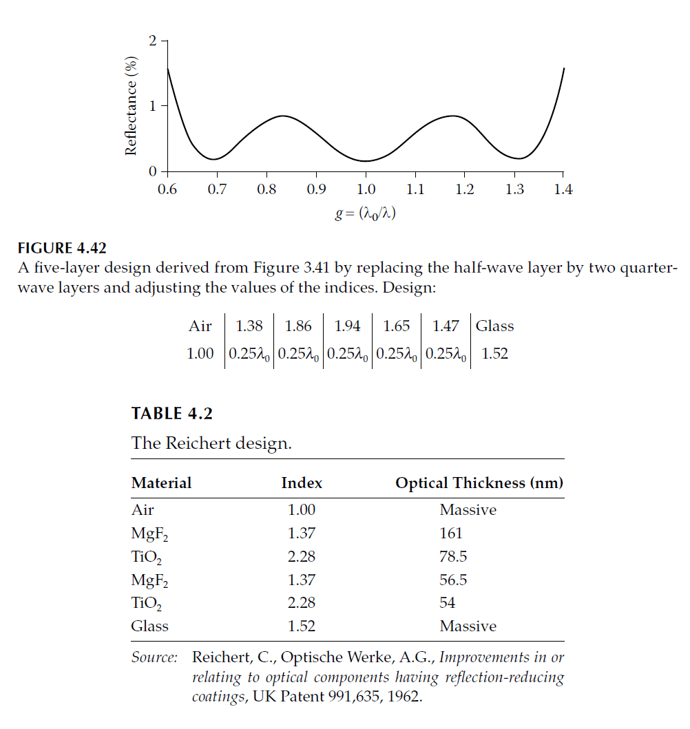
- Five-Layer Designs: Derived by splitting the half-wave layer in quarter-half-quarter coatings into two quarter-waves (Figure 4.39).
- W-Coat Variations: Designs like the “W-coat” use additional intermediate layers to flatten reflectance (Figure 4.31).
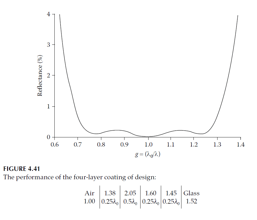
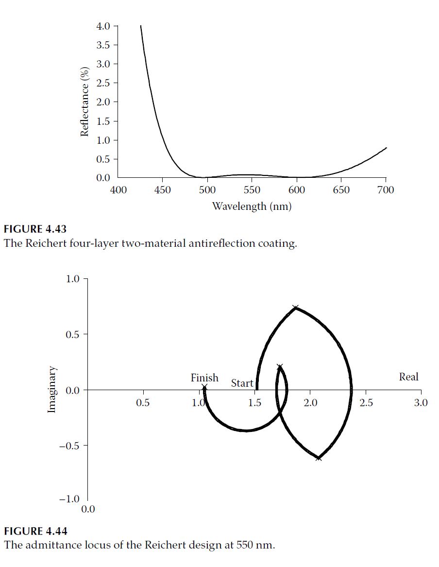
- Reichert Design: A four-layer design with high and low alternate indices is thinner and derived from W-coat principles. The admittance plot (Figure 4.44) and reflectance curve (Figure 4.43) show its performance.

Practical Considerations
- Material Availability: Not all desired indices are readily available, necessitating compromises or innovative designs.
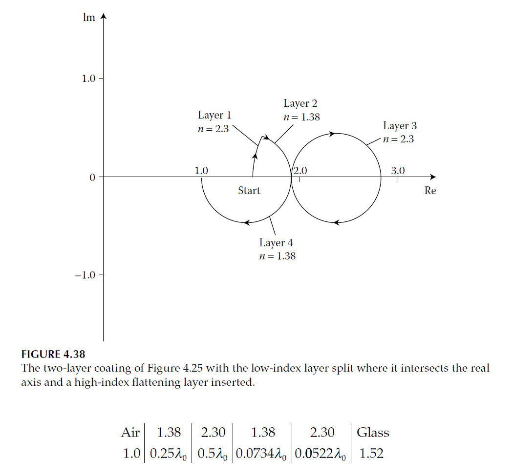
- Angle of Incidence: Coatings optimized for normal incidence often degrade at larger angles. Designs for specific angles (e.g., 45°) consider polarization effects (Figure 4.37).
The development of multilayer antireflection coatings, including three-layer and four-layer designs, represents significant advancements over simpler two-layer structures. Techniques like Thetford’s method and refinements by other researchers enable low reflectance across broad spectral ranges, meeting the demands of modern optical applications.