Little has been written on the subject of gain in optical coatings, perhaps because the topic is not of great practical importance currently. However, there are some interesting and fascinating effects associated with gain, so this section includes some notes on it.
Gain calculations are handled through the extinction coefficient, similar to absorption, but with the coefficient having the opposite sign. This discussion heavily relies on a paper presented at the 2006 Workshop of European Vacuum Coaters.
Admittance Locus Visualization
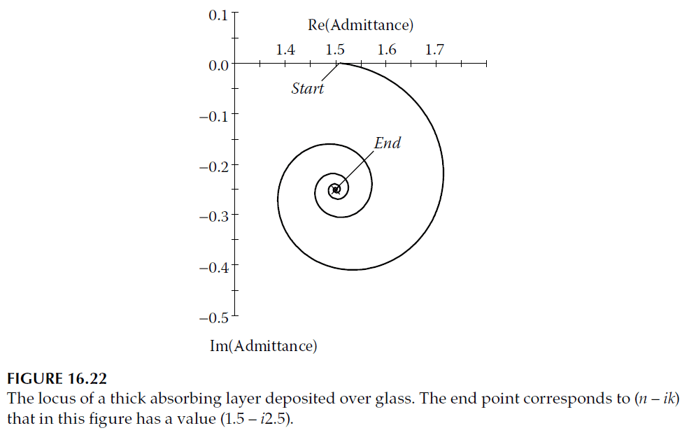
A particularly useful way to visualize the difference between a positive and negative value of \( k \) is through an admittance locus. For a material with loss (\( k > 0 \)), the locus is a gradually collapsing spiral that eventually reaches the point \( (n – ik) \) (Figure 16.22).
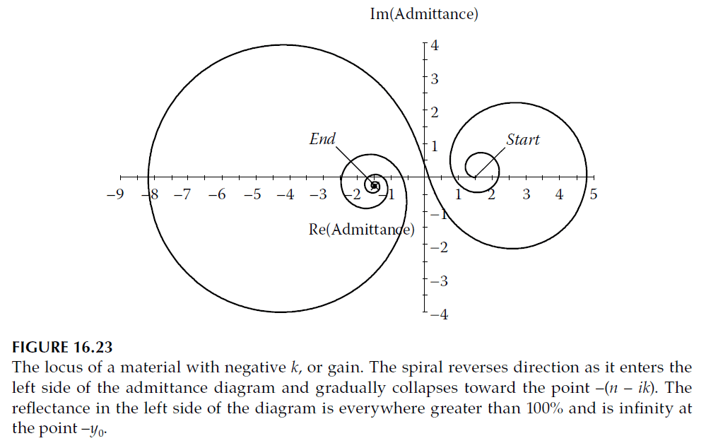
Conversely, for a material with gain (\( k < 0 \)), the spiral opens out. If the material is sufficiently thick, the spiral crosses the imaginary axis, reverses direction, and spirals inward toward \( -(n – ik) \) (Figure 16.23).
The large value of \( k \) in Figure 16.23 is intentionally chosen to clearly demonstrate the spiral, whereas real cases would involve smaller \( k \) and slower spirals.
Behavior of Gain
In real cases, gain results from a population inversion maintained by a pumping process. This gain stabilizes when depletion due to irradiance is balanced by the pumping. Here, we assume very low power levels to avoid the depletion effect.
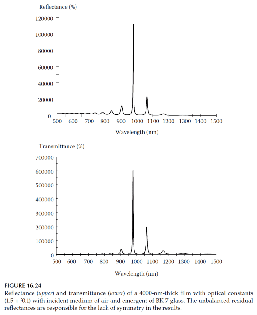
The gain increases transmittance and reflectance, both of which can exceed unity. Figure 16.24 illustrates the behavior of a system with a 4000-nm-thick film having optical constants \( (1.5 + i0.1) \), with air as the incident medium and BK 7 glass as the emergent medium. The high reflection loss at the air interface makes the transmitted output larger than the reflected output, with both exceeding 100%.
Oscillation in the System
By adjusting gain and wavelength, it is possible to achieve infinite reflectance, resulting in system oscillation. The power output determines the ultimate extinction coefficient. If the reflectance is close to \( -y_0 \), spontaneous emission within the film can initiate oscillation. However, conventional thin-film calculations assume an external input, and the effects of spontaneous emission are not accounted for.
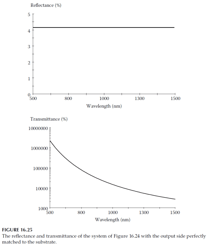
Figure 16.25 demonstrates the behavior when the rear reflectance (e.g., 0.11% for BK 7) is eliminated using an antireflection coating, making the device an ideal amplifier. In practice, irregularities like inhomogeneities or spontaneous emission can destabilize the amplifier, causing the admittance locus to expand suddenly. To maintain stability, the output reflectance must be sufficiently low.
Dielectric Layer Behavior
Dielectric layers added to the left side of the complex plane behave almost normally, with loci forming circular paths centered on the real axis. However, for gain systems, the loci are traced counterclockwise instead of clockwise. Matching the rear surface of the gain layer to the emergent medium introduces unique challenges.
For maximum throughput with an absorbing substrate, the following definition of transmittance applies (Equation 2.80):
\[ T = \frac{4y_0 y \, \text{Re}(Y)}{\text{Re}(Y) [(y_0 + y)(y_0 + Y)^*]} \] where \( y_0 \) is the incident medium admittance, \( y \) is the gain layer admittance, and \( Y \) is the rear surface admittance.
The transmittance is maximized when \( Y \) equals the complex conjugate of \( y_0 \). However, for amplification, this condition is impractical as it risks introducing counter-propagating waves. To avoid standing waves, the exit admittance must equal the characteristic admittance of the gain medium. This ensures the admittance locus is a point, with the reflectance being that of the bulk material.
Antireflection Coatings for Gain
Antireflection coatings for gain layers follow standard principles. However, matching applies only to the specific gain value, and any changes in gain disturb the matching, causing the spiral to reopen.
1. Oblique Incidence
Modified, tilted admittances with the expressions for absorbing materials provided in Equations 9.10 and 9.11. These equations are reiterated below:
\[
\eta_s = \frac{n \cos^2 \vartheta_0 – \sqrt{n^2 – n_0^2 \sin^2 \vartheta_0 – 2ik(n^2 – n_0^2 \sin^2 \vartheta_0)}}{n \cos^2 \vartheta_0 + \sqrt{n^2 – n_0^2 \sin^2 \vartheta_0 – 2ik(n^2 – n_0^2 \sin^2 \vartheta_0)}}
\quad (\text{4th quadrant})
\tag{16.28}
\]
\[
\eta_p = \eta_s (n – ik)^2
\tag{16.29}
\]
The modified admittances are normalized so that the incident medium retains its normal incidence value, making the admittance diagram easier to interpret. These expressions also apply to completely dielectric layers (when \( k = 0 \)), resulting in a simpler form.
Admittance Behavior for Real and Absorbing Layers
If \( n > n_0 \sin \vartheta_0 \), then \( \eta_s \) and \( \eta_p \) are both positive real. As \( \vartheta_0 \) approaches 90°, \( \eta_s \) approaches infinity, while \( \eta_p \) approaches zero. If \( n < n_0 \), \( \eta_s \) and \( \eta_p \) exhibit the opposite behavior, reaching critical values when \( n_0 \sin \vartheta_0 = n \).
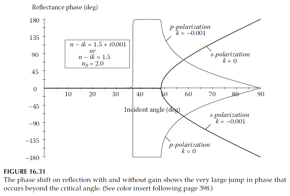
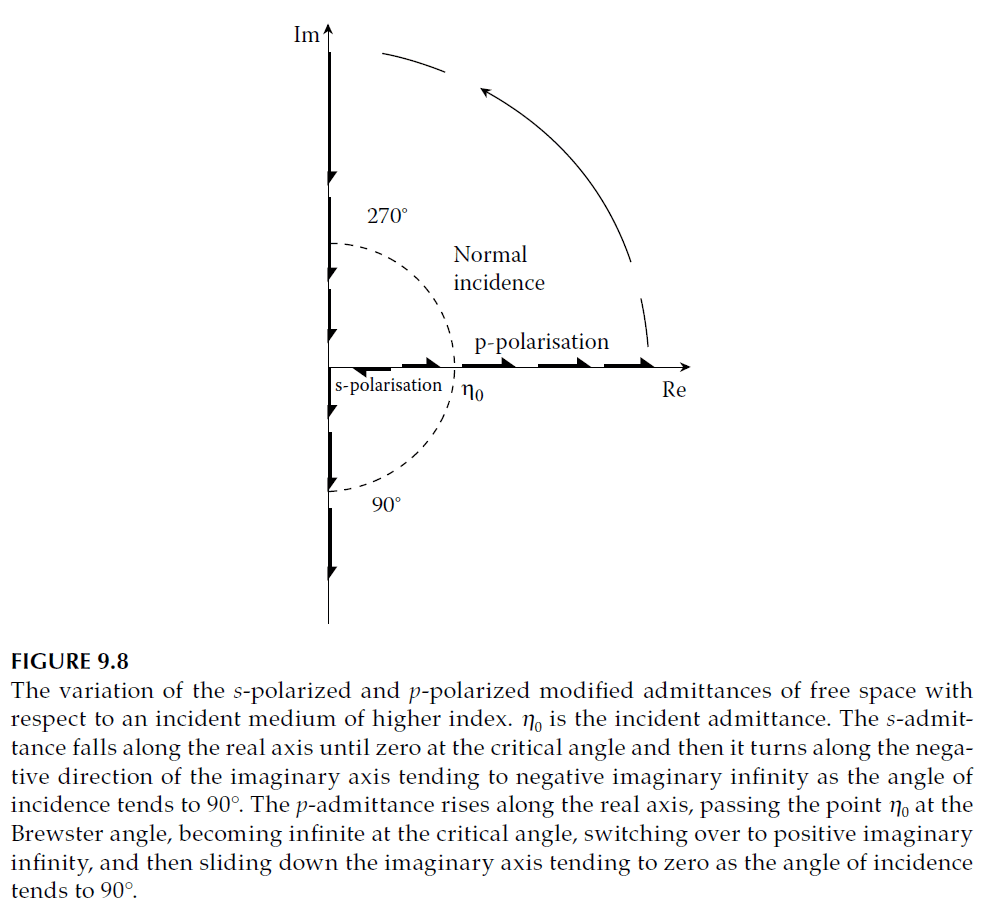
Beyond this critical angle, \( \eta_s \) becomes negative imaginary, sliding toward \( -\infty i \), and \( \eta_p \) transitions to the imaginary axis, moving from infinity to zero. During total internal reflection, the phase shift changes with polarization:
- s-polarization: Moves through the first and second quadrants.
- p-polarization: Moves through the third and fourth quadrants.
This behavior is illustrated in Figure 9.8.
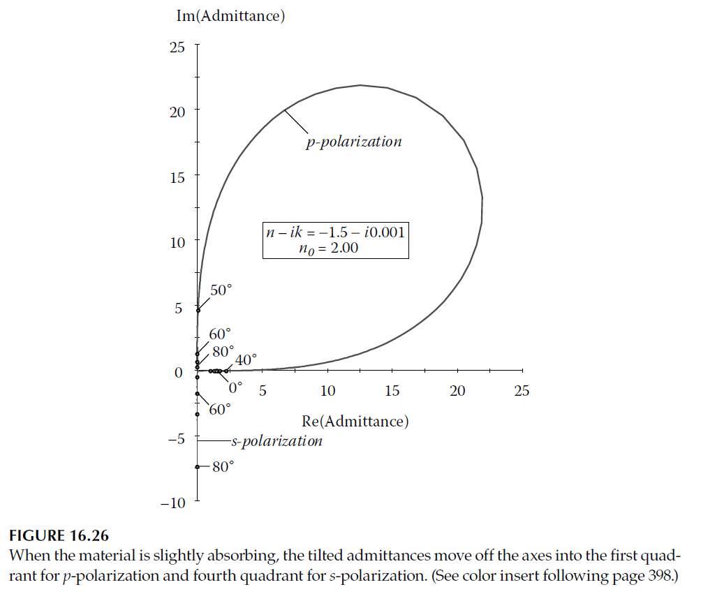
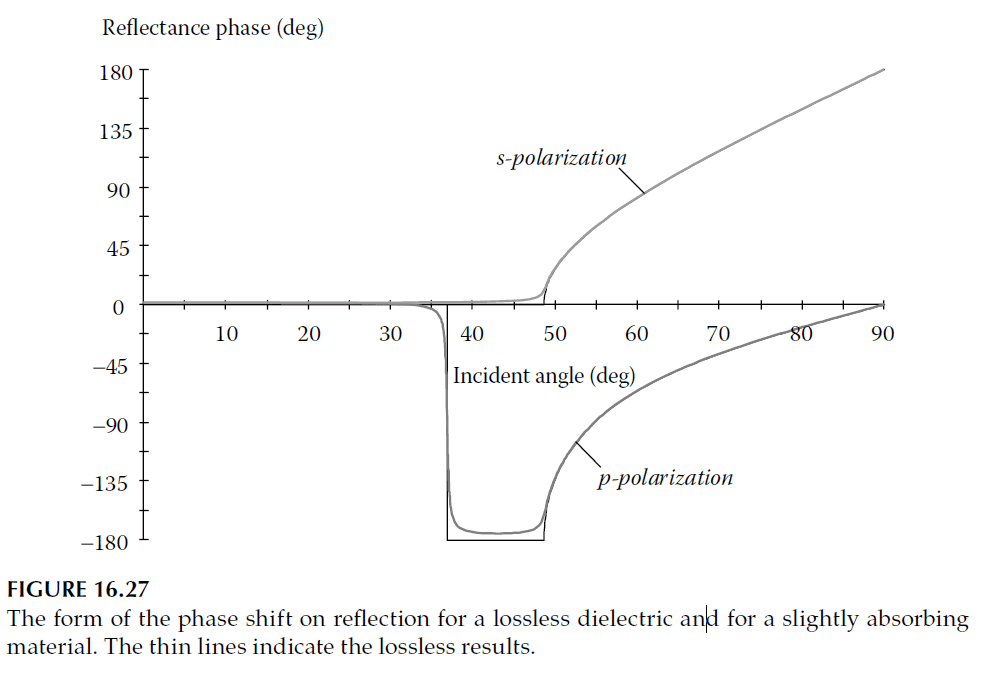
For absorbing materials, the admittance loci deviate slightly, moving off the real and imaginary axes. Figure 16.26 depicts this adjustment, with \( \eta_s \) entering the fourth quadrant and \( \eta_p \) the first. Total internal reflection is replaced by high reflectance, and phase shifts are slightly modified (Figure 16.27).
Admittance with Gain
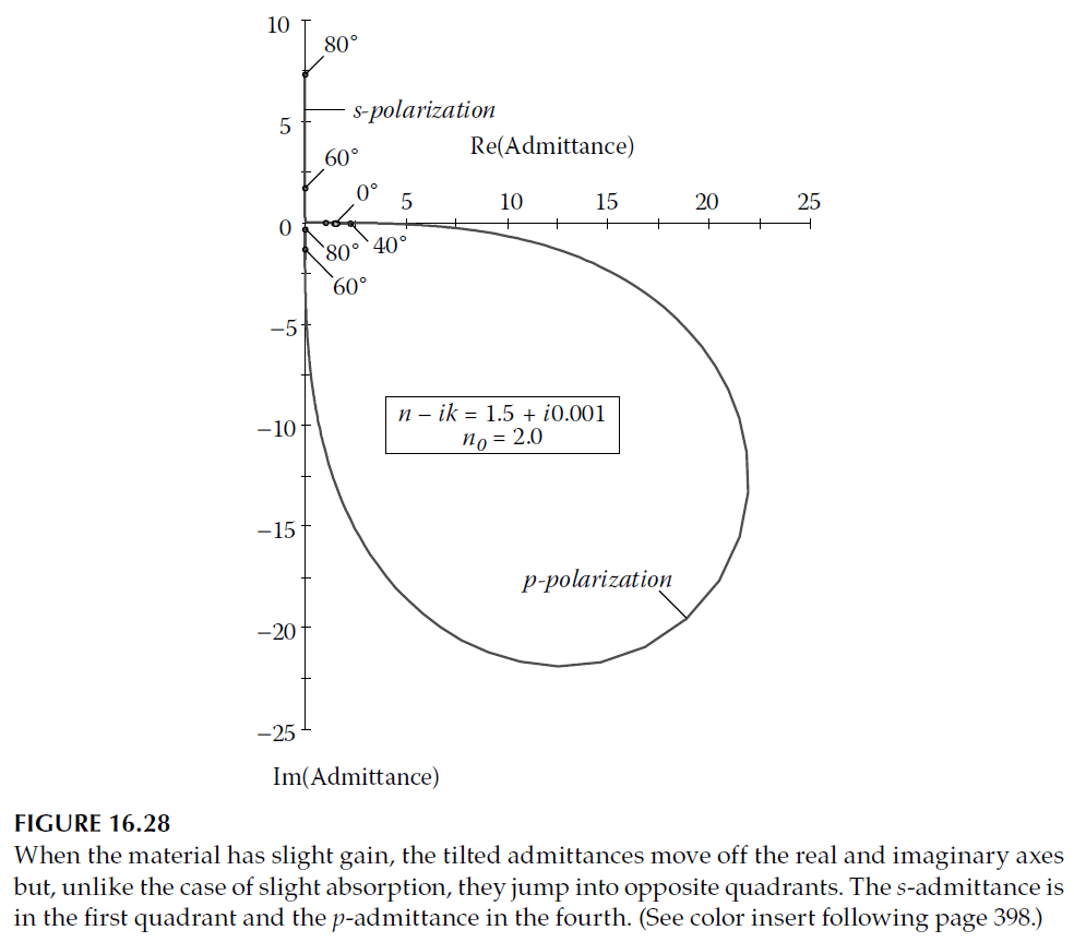
When gain is introduced (\( k < 0 \)), the behavior changes significantly. In Equation 16.28, the term under the square root enters the first or second quadrant, forcing the solution to reside in the first quadrant for physical consistency.
Figure 16.28 shows how tilted admittances behave when the incident medium index exceeds that of the emergent medium. Here, the loci invert compared to Figure 16.26.
Surface Plasmon Resonance and Gain
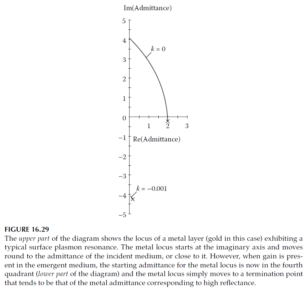
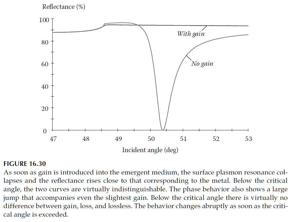
Surface plasmon resonance undergoes notable changes in gain media. For p-polarization, the metallic admittance locus normally leading to plasmon resonance cannot move to the incident medium’s admittance point.
Figure 16.29 compares the admittance loci with and without gain, showing the resonance disappears entirely in the presence of gain.
Figure 16.30 illustrates how reflectance performance changes due to gain.
To understand these effects, consider the complete expression for a wave in a gain medium:
\[ E = E_0 \exp \left[ i \frac{\omega}{c} \left( \frac{\pi}{\lambda} \sin \vartheta_0 \xi z + i \zeta z \right) \right] \tag{16.30} \]
Here:
- \( \xi \) and \( \zeta \) are positive.
- \( \xi \): Governs the phase propagation direction.
- \( \zeta \): Controls amplitude increase along \( z \).
Such waves, where planes of constant amplitude and phase are no longer parallel, are termed inhomogeneous waves. For gain, the wave increases exponentially into the emergent medium, skimming close to the interface at an angle \( \arctan[\xi / (n_0 \sin \vartheta_0)] \). This effect contrasts with absorbing emergent media, where the wave decays exponentially.
Gain-Induced Phase Jump
The phase jump due to gain, described by A.E. Siegman, results from this unique behavior. Although small, gain values of \( 10^{-20} \) at 1000 nm—representing a signal increase of 1 dB across vast distances—can induce reflectance changes of nearly 100%. Brudny further explains this phenomenon in the context of evanescent tunneling.
