Designing Filters for Fluorescence Microscopy
The primary aim in designing filters for fluorescence microscopy is to create filter sets—usually including an excitation filter, an emission filter, and a dichroic beamsplitter—that optimize image contrast and preserve image quality. Key factors that impact image contrast include:
- Absolute Image Brightness
- Signal-to-Noise Ratio (S/N): The brightness of the fluorescent signal relative to background noise.
- Color Balance: Perceived by the eye, though this is less critical for visual or photographic observations.
For high contrast, filters must offer high throughput (a combination of wide bandwidth and high transmittance) and low cross-talk. High S/N alone won’t improve contrast if the image brightness is insufficient for clear detection. Achieving optimal contrast can vary based on the application, so filter designers need a conceptual understanding of each application to incorporate the most relevant information.
Maintaining Image Quality
Image quality is ensured by meeting the optical quality standards at each point where a filter is used in the microscope. This requires a strong foundation in microscope optics, along with knowledge of specific application requirements. This is especially important with the expanding applications in microscopy, leveraging advanced technologies like laser-based illumination and sample manipulation, digital imaging, computer-assisted positioning, and ultra-sensitive detection devices.
Additionally, filter designers must be mindful of the physical dimensions specific to different microscope brands and models, ensuring compatibility across various systems.
Image Contrast
To optimize a filter set for a specific fluorochrome, we can examine the process using FITC-stained specimens as an example. FITC, a commonly used fluorescent dye, has well-defined excitation and emission spectra, and filter sets are designed to maximize the dye’s fluorescence signal while minimizing background noise.
- Excitation Filter: The excitation filter is designed to transmit only the wavelengths that effectively excite FITC, usually in the blue range, while blocking other wavelengths. This ensures that the specimen receives only the excitation light FITC requires, enhancing its fluorescence.
- Dichroic Beamsplitter: The dichroic beamsplitter is tailored to reflect the excitation wavelengths into the objective while transmitting the emission wavelengths from the FITC-stained specimen. This selective reflection and transmission helps prevent unwanted excitation light from reaching the detector, improving signal clarity.
- Emission Filter: The emission filter is engineered to transmit the specific wavelengths of light that FITC emits (in the green range) while blocking the excitation wavelengths. This isolates the FITC fluorescence signal from background noise, increasing the signal-to-noise ratio (S/N) and enhancing image contrast.
This approach, customized for FITC’s unique spectral properties, enables the filter set to provide high contrast and clarity for imaging, illustrating the importance of tailored filter design for different fluorochromes.
Fluorescence Spectra and Filter Design
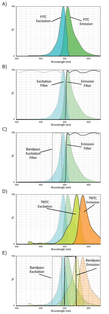
The most crucial factor in designing a filter set is understanding the spectral characteristics of the fluorochrome, which include the excitation and emission spectra, as illustrated in Figure 18A. If only these spectra were considered, the optimal approach would be to use a shortpass excitation filter that transmits the full excitation spectrum and a longpass emission filter that transmits the entire emission spectrum. An idealized pair of FITC filters with these characteristics is shown in Figure 18B. In reality, however, filters require a greater separation between the cut-on and cut-off wavelengths due to slope limitations, and the shortpass filter’s cut-off would typically fall within the UV range.
However, several additional factors must be addressed in practical applications:
- Autofluorescence and Photobleaching: Using a shortpass excitation filter, especially one that transmits UV, can increase autofluorescence in specimen tissues, which is common in pathology and can degrade image quality. Moreover, UV light, with its higher quantum energy, accelerates photobleaching of the fluorochrome and can potentially cause photodamage to the specimen. To mitigate these effects, a bandpass excitation filter that transmits only the peak excitation region of FITC is preferred (see Figure 18C), balancing adequate intensity with minimal autofluorescence and photodamage.
- Dual-Fluorochrome Imaging: If a second fluorochrome is present, such as TRITC (Figure 18D), which has some excitation efficiency in the blue, a longpass emission filter for FITC may allow undesired TRITC emission in the orange range to pass through. This cross-talk can interfere with imaging, particularly with monochrome cameras that lack color differentiation. To prevent this, a bandpass emission filter can be used to specifically isolate FITC’s peak emission band (shown in Figure 18E), reducing cross-talk and enhancing contrast.
The filters in Figure 18E represent examples of 49-series ET filters, which provide a selective, narrow band for FITC. In cytometric applications, where high selectivity between fluorochromes is often prioritized over brightness, even narrower bands are frequently used to maximize fluorochrome distinction.
Light Sources in Fluorescence Microscopy
In fluorescence microscopy, light sources vary widely in spectral output, affecting how filters are designed for optimal contrast and signal detection. Here’s an overview of common light sources used in fluorescence microscopy:
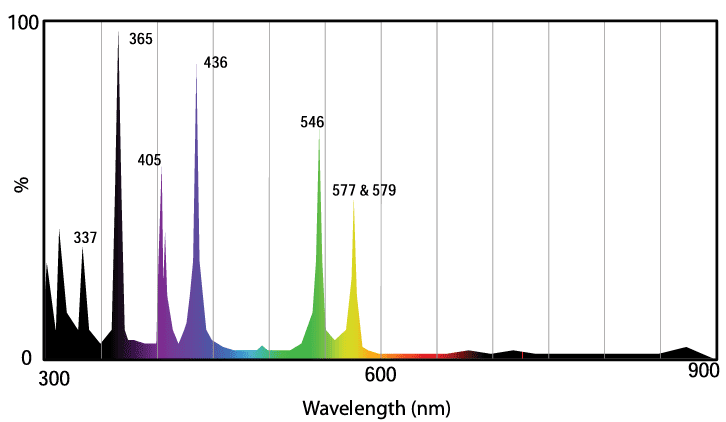
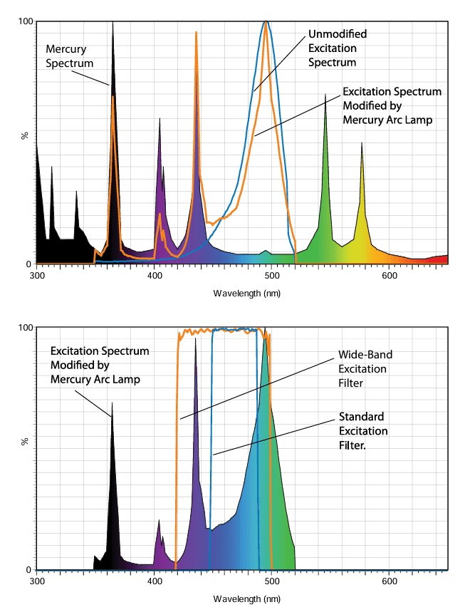
- Mercury Arc Lamps: Mercury arc lamps are favored for their high brightness (luminance) in the UV and visible ranges. Their light spectrum (Figure 19) is concentrated in narrow bands or “lines,” about 10 nm wide. General-purpose filter sets should have excitation filters that transmit one or more of these lines, although excluding certain lines can sometimes improve S/N by reducing autofluorescence. For example, excluding the 436 nm line when using FITC may prevent excessive autofluorescence. However, for low-fluorescence applications or blue-shifted FITC spectra, including the 436 nm line may enhance detection.
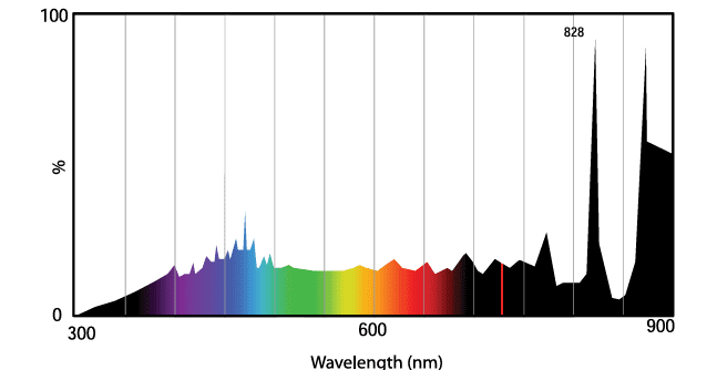
- Xenon Arc Lamps (Figure 21): Xenon arc lamps provide a relatively continuous spectrum in the visible range, making them suitable for quantitative spectral analysis of dyes and specimens. However, they are less bright than mercury lamps of similar wattage, and their high IR output necessitates filters with strong blocking above 800 nm. Additionally, xenon lamps have a broader arc and more IR output, which can introduce higher thermal loads, requiring filters designed for increased durability.
- Metal-Halide Short-Arc Lamps: These lamps share similarities with mercury arc lamps but offer higher intensity across main emission lines. Metal-halide lamps have a longer lifespan (up to 2000 hours) and come with precise, stable alignment due to their housing and integral elliptical reflector. Despite these advantages, they are not significantly brighter than xenon lamps due to their larger arc size, and like xenon lamps, they also have high IR output, which can add heat-related challenges for filter design.
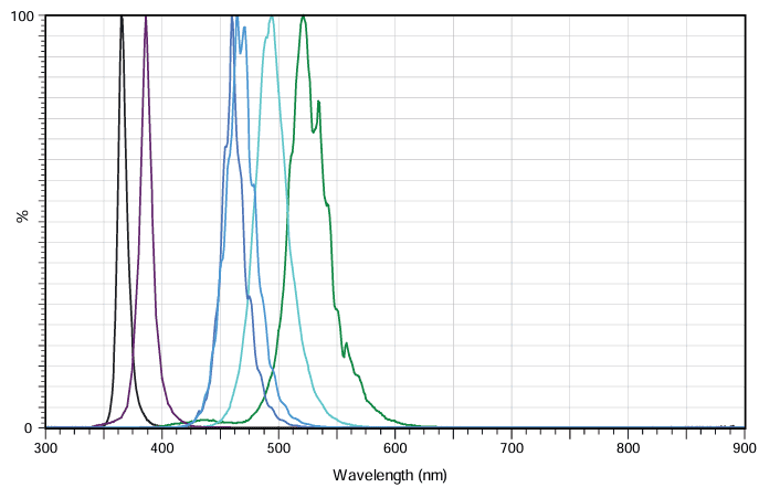
- Light-Emitting Diodes (LEDs): LEDs are increasingly popular, particularly in educational microscopes, because they emit light within narrow spectral bands (FWHMs of 10-40 nm) (Figure 22). This characteristic reduces the need for extended blocking in excitation filters and sometimes even eliminates the need for an excitation filter with fluorochromes having large Stokes shifts. However, most applications with narrow Stokes shifts still require standard excitation/emission filter pairs. Advantages of LEDs include long life (10,000-50,000 hours), consistent output over time, and precise control of on/off and intensity. The primary limitation has been brightness, though recent improvements have made LEDs nearly as bright as arc lamps within their narrow bands. However, LEDs have limited spectral bands available, particularly in green (~546 nm), which can impact multi-channel applications.
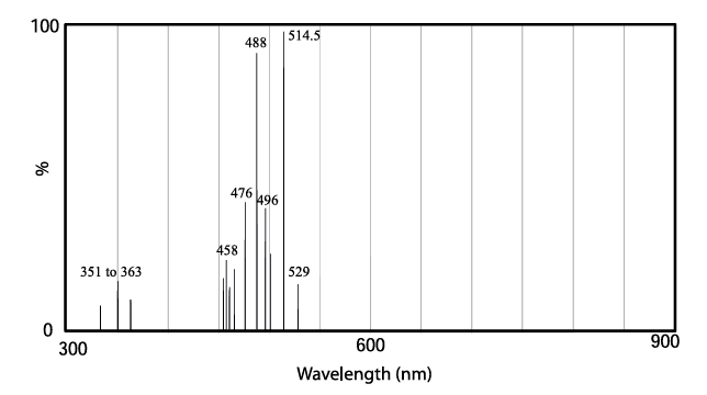
- Lasers: Lasers are widely used in confocal fluorescence microscopy due to their extremely high brightness in narrow, usually monochromatic bands (Figure 23). Their coherent light makes them less suitable for wide-field microscopy, as achieving uniform sample illumination is challenging. Special filter designs are needed for laser-based illumination to manage these unique requirements effectively.
Each light source type has specific strengths and limitations, and selecting the appropriate filter set based on the source’s characteristics is essential to maximize fluorescence contrast and signal quality in microscopy.

Designing Excitation Filters for Detector Sensitivity
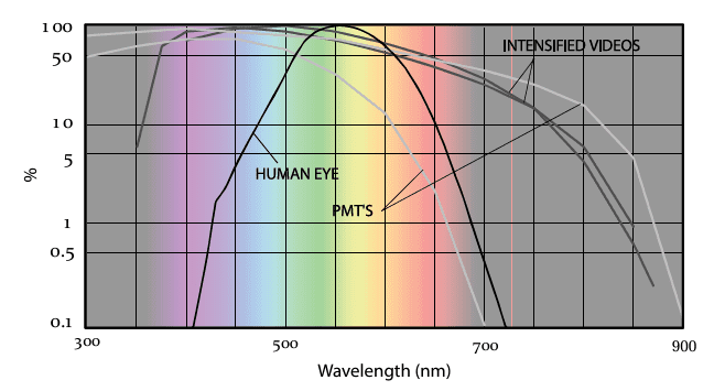
When designing excitation filters, they must effectively block out-of-band light that could interfere with the detector’s sensitivity. Arc and filament lamps emit across the near-UV, visible, and IR ranges, so filters need strong attenuation across the entire detector sensitivity range. However, with laser illumination, the excitation filter’s blocking range can be limited to the laser’s output. For instance, IR blocking isn’t necessary for argon-ion lasers (see Figure 23). Detector sensitivity spectra (Figure 24) also inform filter design. While standard silicon photodiodes and CCDs detect up to 1100 nm, their sensitivity declines by 1200 nm. Intensified silicon detectors, like those with microchannel plates, have similar sensitivity to the intensified video spectra.
In general, out-of-band light should be blocked by the excitation filter rather than the emission filter for several reasons:
- Reduced Specimen Exposure: Less exposure to unnecessary radiation reduces potential damage.
- Improved Optical Quality: Emission filters perform better with fewer blocking components, enhancing imaging quality.
- Space Efficiency: Microscope designs often limit space for emission filters, so reducing added components is beneficial.
In some cases, such as UV excitation, achieving extensive blocking in the excitation filter can reduce its peak transmission. For these scenarios, IR blocking in the emission filter can be more effective. In visible photographic applications, IR blocking is also critical since built-in light meters may detect IR, potentially skewing exposure times.
Selecting Dichroic Beamsplitters for Filter Sets
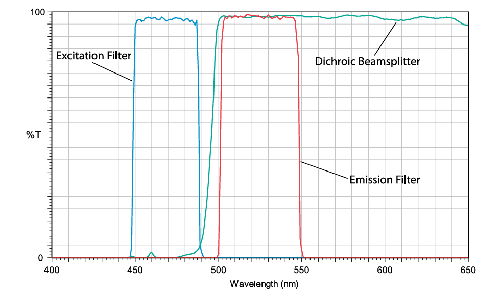
The final step in designing a fluorescence filter set is to choose a dichroic beamsplitter that aligns with the spectra of the excitation and emission filters. Ideal beamsplitters provide high reflectance in the excitation band while maintaining high transmittance in the emission band, which maximizes signal and enhances contrast by minimizing background noise. With advanced coating methods, like modified magnetron sputtering, beamsplitters can now achieve greater than 95% reflectance in the excitation band and over 95% transmission in the emission band.
However, due to the 45-degree angle of incidence, these coatings can introduce polarization, which filter designers must carefully manage to minimize. Beamsplitters for optical systems, like microscopes, typically have one or two specialized coatings directly applied to the glass substrate, making them delicate and requiring careful handling. The side facing the light source and specimen, called the front surface, is often marked by the manufacturer to ensure proper orientation, as determining the front side can be challenging without such guidance.
Figure 25 illustrates a completed filter set design for FITC, showing the excitation filter, emission filter, and matched dichroic beamsplitter.
