Introduction to Optical Filters
An optical filter selectively transmits specific portions of the optical spectrum while blocking others. Widely used in fields such as microscopy, spectroscopy, chemical analysis, and machine vision, Notch Optics offers a range of optical filters in various types and precision levels. This guide provides an overview of the different technologies used to create Notch Optics filters, key specifications, and the types of filters available.
Key Optical Filter Terminology
Optical filters share some specifications with other optical components, but there are unique specifications that are essential for choosing the right filter for a given application.
Central Wavelength
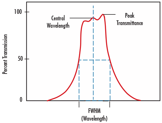
The Center Wavelength (CWL) in bandpass filters marks the midpoint of the spectral bandwidth over which the filter transmits. Traditional coated filters often reach maximum transmission near the center wavelength, while hard-coated filters provide a more uniform transmission across the bandwidth.
Bandwidth
Bandwidth refers to the range of wavelengths that can pass through a filter, also known as Full Width at Half Maximum (FWHM).
Full Width-Half Maximum (FWHM)
FWHM describes the spectral range over which a bandpass filter transmits light, measured from the wavelengths at 50% of the maximum transmission. Filters with a FWHM of 10nm or less are narrowband and are commonly used for laser applications, while broader FWHM ranges are often used in machine vision and fluorescence microscopy.
Blocking Range
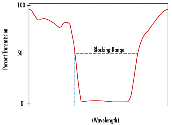
The blocking range indicates the wavelength interval where the filter attenuates energy, typically specified by optical density.
Slope
Slope is a parameter for edge filters (such as shortpass or longpass filters) that describes the filter’s transition from high blocking to high transmission. Notch Optics typically defines slope as the range from the 10% to the 80% transmission points.
Optical Density
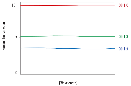
Optical Density (OD) indicates the level of energy blocked by a filter. Higher OD values mean greater blocking, ideal for applications like laser separation and clean-up, machine vision, and chemical detection.
\[\text{Percent Transmission}=T=10^{-OD}\times100\%\]
\[OD=-\log\left(\frac{T}{100\%}\right)\]
Dichroic Filters
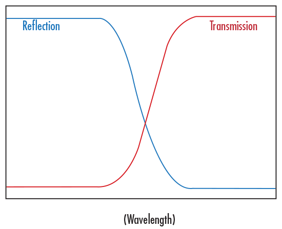
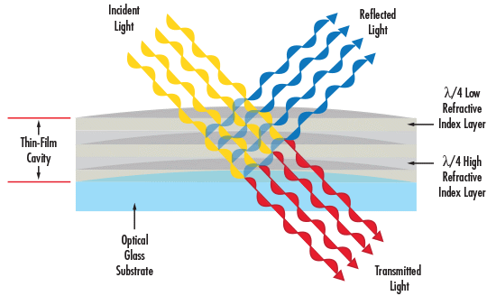
Dichroic filters reflect or transmit light depending on wavelength. They are commonly used in longpass and shortpass applications, with specific wavelengths transmitted while others are reflected or absorbed.
Cut-On and Cut-Off Wavelengths
Cut-On Wavelength
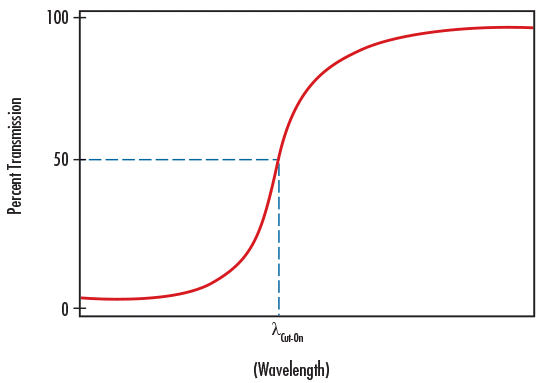
In longpass filters, the cut-on wavelength is where transmission reaches 50% throughput.
Cut-Off Wavelength
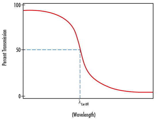
In shortpass filters, the cut-off wavelength is where transmission drops to 50% throughput.
Optical Filter Fabrication Techniques
Filters generally either absorb unwanted light through colored glasses or dyes or reflect it using interference coatings. Notch Optics primarily uses interference coatings for superior performance and durability. Hard-coated filters consist of a single substrate with dense, durable coatings meeting military standards for durability, making them ideal for precision applications. Traditional coated filters, typically multi-layered and laminated, are well-suited for laboratory use but have limited environmental stability. Absorptive filters use dyes or compounds in the substrate to control spectral properties and are commonly used in illumination and sensing.
Absorptive and Dichroic Filters
Filters are classified as absorptive or dichroic based on how they filter light. Absorptive filters block light based on the glass substrate’s absorption properties and are effective in applications needing consistent performance across angles. Dichroic filters, on the other hand, reflect unwanted wavelengths and are highly angle-sensitive, often used to separate wavelengths into different sources.
Exploring Dichroic Bandpass Filters
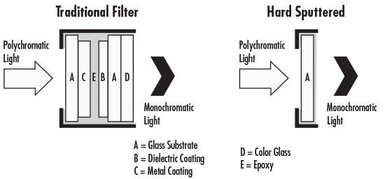
Dichroic bandpass filters are produced using traditional or hard-sputtered techniques. Traditional filters use multiple substrate layers, which can reduce transmission due to light absorption and reflection. Hard-sputtered filters apply high and low-index materials to a single substrate, creating a thinner, high-transmission filter ideal for precision applications.
Types of Optical Filters
Optical filters come in various types, each with unique properties for controlling light effectively:
- Bandpass Filters: Transmit a specific range of wavelengths while blocking others.
- Dichroic Beamsplitters: Divide a light beam into two beams with different wavelengths.
- Notch Filters: Transmit all wavelengths except a narrow band which is blocked.
- Edge Filters: Transmit wavelengths either longer or shorter than a specific cutoff wavelength.
These filters are integral components in optical systems across multiple fields, enabling detailed scientific study, medical diagnostics, and technological advancements.
Applications of Optical Filters
Optical filters find widespread use in:
- Fluorescence Microscopy: Facilitates detailed imaging and analysis by distinguishing different tissue types based on fluorescence.
- Medical Imaging: Essential for PCR testing, cancer screening, and DNA sequencing devices.
- Optical Spectroscopy: Enables precise identification of material composition through wavelength isolation.
- Industrial Applications: Used in machine vision and quality control to detect defects and identify objects.
Example 1: Color Match Imaging
Monochrome cameras cannot inherently distinguish different colors, but adding a color filter significantly enhances contrast between objects. A useful guideline is that a color filter will lighten objects of the same color while darkening those of opposing colors.
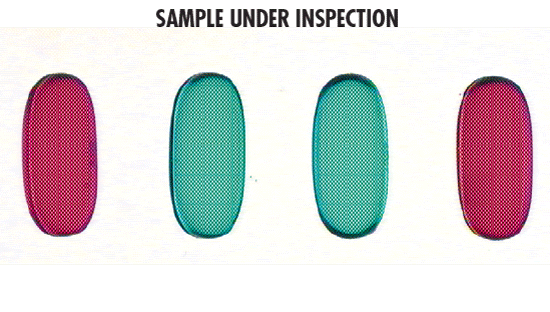
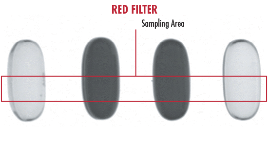
For instance, imagine imaging two red and two green pills with a monochrome camera. Figures 9a – 9d display images of the sample under different filters. Without a filter (Figure 9b), the monochrome camera cannot differentiate red from green, making inspection on a production line challenging.
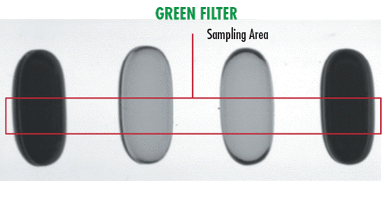
However, with a red filter (Figure 9c), green pills appear gray due to increased contrast, making them easily distinguishable from red pills. Similarly, using a green filter (Figure 9d) causes red pills to appear gray, aiding in clear differentiation.

Example 2: Raman Spectroscopy
In Raman spectroscopy, a few specific filters can greatly enhance results: laser line bandpass, rugate notch, or laser line longpass filters. For optimal performance, use filters with bandwidths as narrow as 1.2nm and optical densities of OD 6.0.
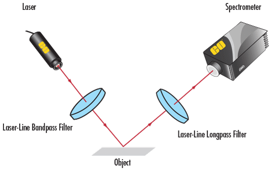
A laser line bandpass filter is positioned in the optical path between the laser and the sample, blocking ambient light and allowing only the laser wavelength to pass. When light interacts with the sample, Raman scattering shifts the wavelength, generating numerous low-intensity signals.
To block the high-intensity laser light effectively, a notch filter centered close to the laser wavelength is essential. If Raman excitation modes occur very close to the laser line, a laser line longpass filter can serve as an effective alternative. Figure 10 depicts a typical Raman spectroscopy setup.
Optical filters are used across countless applications beyond color match imaging and Raman spectroscopy. They play a vital role in nearly every facet of the optics, imaging, and photonics industries. Gaining knowledge of optical filters’ fabrication techniques, essential terminology, and the various types available today enables selecting the most suitable filter for any specific setup.
Why Use Optical Filters?
Optical filters are employed for:
- Isolating Specific Wavelengths: Essential for precise data collection and analysis in scientific and medical fields.
- Enhancing Image Clarity: Improves signal-to-background ratios by blocking unwanted light.
- Improving Visibility: Enhances observation of celestial objects and protects against harmful radiation.
Cleaning Optical Filters
Proper cleaning of optical filters is essential for maintaining their performance. Refer to manufacturer guidelines or instructional resources for detailed cleaning procedures.
Filters can be cleaned using the same methods as lenses or mirrors. The preferred method is to use Compressed Air or an Air Blower to remove dust. If additional cleaning is required, then using a Cotton-Tipped Swab or Lens Tissue saturated with Reagent-Grade Isopropyl Alcohol, Reagent-Grade Acetone, or Lens Cleaning Solution will work too.
6 Tips for Handling Filters
- Always wear gloves or finger cots. The oil on your fingertips can sometimes damage the coating on optics, and if a fingerprint is left on an optical surface for a long time, it can become a permanent stain.
- Always handle optics by the edges. Never touch the optical surface with your fingertips, even while wearing gloves.
- Never handle optics with metal tools. Reduce the chance of damage by using wooden, bamboo, or plastic tools to handle optics. Vacuum pens are handy for small optics.
- Always place an optic on a clean soft surface, especially if the optical surface is convex. Resting on a hard or dirty tabletop can cause scratches on the optical surface.
- To store optics, wrap them individually in clean, lint-free lens tissue and place in a low humidity environment. Never store unwrapped optics together in a box or bag, as contact between the optics will cause damage. Never store optics with heavier items on top of them.
- Never blow on the optic. It is also recommended to not chew gum or talk while handling optics to prevent saliva contamination. Saliva particles will often stain the surface.
Conclusion
Optical filters are indispensable tools in modern technology, enhancing our ability to observe, analyze, and protect against light in various scientific and industrial applications.
