Designing coatings that avoid polarization issues is significantly more challenging than designing polarizers. This is because changes in the phase thickness of layers and optical admittances are fundamental and unavoidable. Therefore, the best achievable outcome is arranging the layer sequence to deliver similar performance for both p- and s-polarization. However, the broader the range of angle of incidence or wavelength, the more difficult this task becomes. Current techniques only operate effectively over narrow ranges of wavelength and angle of incidence. The most useful analytical techniques for such designs were devised by Thelen.
1. Edge Filters at Intermediate Angles of Incidence
This section is based on Thelen’s important work, though the original expressions have been modified here for consistency with the rest of this text. Care should be taken when comparing this section with Thelen’s paper, as the variable \(x\) is defined slightly differently.
At intermediate angles of incidence, where the p-reflectance is not significantly degraded, the primary effect of edge filters operating at oblique incidence is the splitting between the two polarization planes. This splitting limits the achievable edge steepness for unpolarized light. While edge filters with limited pass regions can be constructed from band-pass filters, these too suffer from polarization splitting: the bandwidth for s-polarized light narrows, while for p-polarized light, it expands.
However, a technique exists to displace the pass bands of a band-pass filter, aligning one pair of edges to create an edge filter of limited extent that has no polarization splitting at a specific angle of incidence. This is achieved by adjusting the relative phase shifts between s- and p-polarized light reflected by the filter’s stacks, typically by adding or removing material. With the correct adjustment, the edges can be made to coincide for one specific angle of incidence. As the angle deviates from this design value, the splitting gradually reappears.
Design Techniques
Instead of applying this technique exactly as described, symmetrical periods can be used to design multiple-cavity filters. A typical multiple-cavity filter design can be represented as:
\[
\text{Incident Medium | Matching (Symmetrical Stack)}^q \text{ Matching | Substrate.}
\]
The symmetrical stack can be represented by a matrix of the form:
\[
\begin{bmatrix}
N_{11} & N_{12} \\
N_{21} & N_{22}
\end{bmatrix}.
\]
The passband edges occur where:
\[
N_{11} = N_{22} = \pm 1.
\]
This condition must be satisfied for the appropriate angle of incidence.
A symmetrical period can be constructed using a quarter-wave stack of \(2x + 1\) layers, with two identical outer layers added, one on either side:
\[
fB A B A B \ldots A fB,
\]
where \(A\) and \(B\) are quarter-wave layers, and \(f\) is a correction factor applied to the outermost layers to adjust their thickness. The matrix for this system is given by \(fB M fB\), where \(M\) represents the inner stack:
\[
M =
\begin{bmatrix}
\cos \alpha & i \sin \alpha / \eta_B \\
i \eta_B \sin \alpha & \cos \alpha
\end{bmatrix}.
\]
The passband edges for each polarization are defined by:
\[
N_{11} = \cos 2\alpha – 0.5 \left( \frac{\eta_B}{\eta} – \frac{\eta}{\eta_B} \right) \sin 2\alpha = \pm 1.
\tag{9.28}
\]
This condition must hold for both polarization planes to align the passband edges. While quarter-wave stacks are commonly used, other thicknesses can also work, with trial and error required to satisfy Equation 9.28. A computer can greatly assist in this process.
Example Design
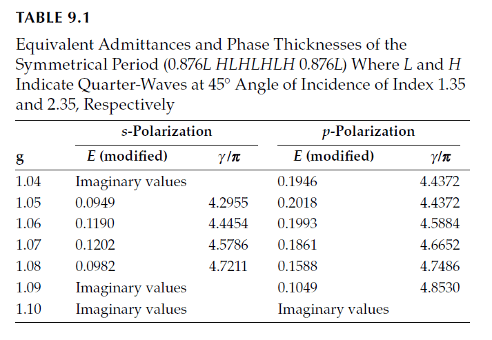
Consider the design of a longwave-pass filter at \(45^\circ\) incidence in air with a symmetrical period:
\[
fL H L H L H L H fL,
\]
where \(H\) has an index of 2.35 and \(L\) an index of 1.35. The inner stack consists of 7 layers (\(2x + 1\)), so \(x = 3\). Modified admittances for this combination are:
\[
\eta_{Hs} = 3.1694, \quad \eta_{Ls} = 1.6264, \quad \eta_{Ss} = 1.9028, \quad \eta_{As} = 1.0000,
\]
\[
\eta_{Hp} = 1.7425, \quad \eta_{Lp} = 1.1206, \quad \eta_{Sp} = 1.2142, \quad \eta_{Ap} = 1.0000.
\]
From these:
\[
P_s = 15.201, \quad P_p = 10.535, \quad Q_s = 7.211, \quad Q_p = 1.0000.
\]
The solution for \(\sin 2\alpha\) yields \(\pm 0.1480\). Two solutions for \(2\alpha\) near \(\pi\) (second and third quadrants) are:
\[
2\alpha = \pi \pm 0.1485 \implies 3.2901 \text{ or } 2.9931.
\]
These correspond to:
\[
f = \frac{(3.2901 / 2)}{(\pi / 2) – 0.1375} = 1.148, \quad f = \frac{(2.9931 / 2)}{(\pi / 2) + 0.1375} = 0.876.
\]
The second solution corresponds to the desired longwave-pass filter.
Final Design
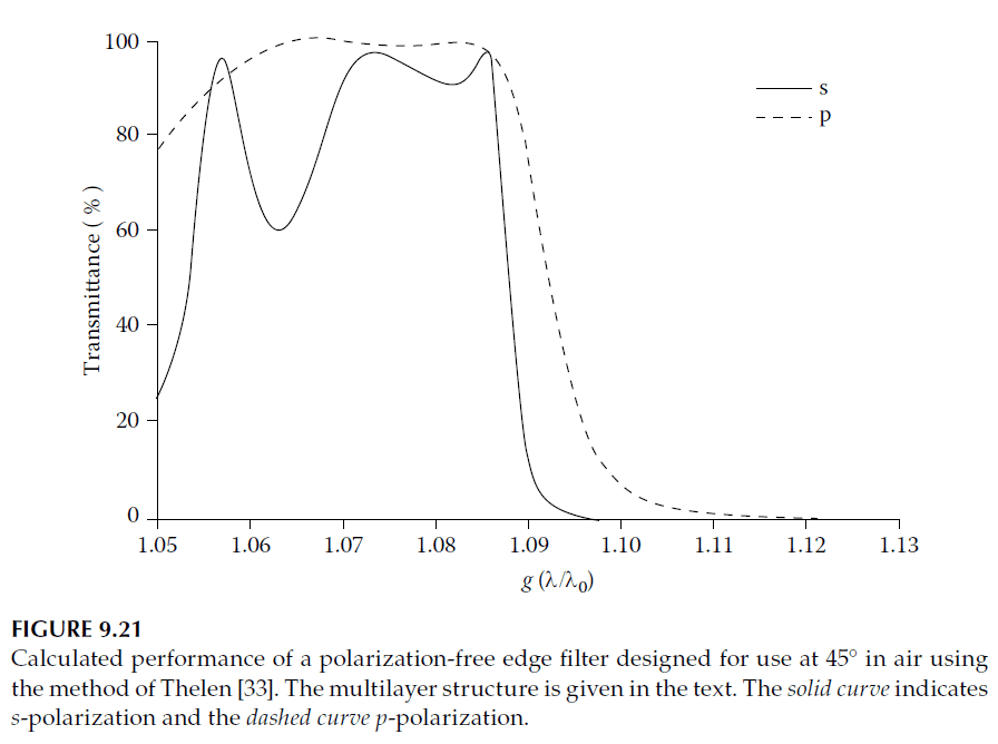
To match the admittances, additional layers are added and adjusted for \(g = 1.08\). The final design, with all thicknesses expressed for normal incidence, is:
\[
\text{Air | (0.971H 1.087L)}^2 \text{ (1.028L (1.049H 1.174L)}^3 \text{1.049H 1.028L)}^q \text{ (1.087L 0.971H)}^2 \text{| Glass.}
\]
Performance with \(q = 4\) is shown in Figure 9.21. The edge steepness is greater for s-polarization, with the two edges coinciding at their upper ends. Adjusting \(f\) can move this point of coincidence. Thelen provides further examples, including designs based on non-quarter-wave thicknesses.
2. Reflecting Coatings at Very High Angles of Incidence
Reflecting coatings operating at very high angles of incidence experience significant reductions in reflectance for p-polarization. This is particularly true for coatings embedded in glass, such as cube beam splitters, which are inherently well-suited for polarizers. The unfavorable admittances for p-polarized light result in reduced reflectance, necessitating a large number of layers—far more than what is typically required at normal incidence. Simultaneously, the s-reflectance must be reduced; otherwise, it would greatly exceed the achievable reflectance for p-polarization.
A method devised by Thelen provides a framework to address this challenge. For additional insights into designing reflecting coatings at oblique incidence using symmetrical periods, the work of Knittl and Houserkova is recommended.
Admittances of Quarter-Wave Stacks
For a quarter-wave stack at normal incidence, the surface admittance \(Y\) is given by:
\[
Y =
\begin{cases}
\frac{y_{\text{sub}}^2}{y_1^2} \cdot \frac{y_3^2}{y_2^2} \cdot \frac{y_5^2}{y_4^2} \cdots, & \text{if the number of layers is even}, \\
\frac{y_1^2}{y_{\text{sub}}^2} \cdot \frac{y_3^2}{y_2^2} \cdot \frac{y_5^2}{y_4^2} \cdots, & \text{if the number of layers is odd}.
\end{cases}
\tag{9.34}
\]
Here, \(y_{\text{sub}}\) represents the admittance of the substrate. The reflectance is calculated as:
\[
R = \left| \frac{y_0 – Y}{y_0 + Y} \right|^2,
\]
where \(y_0\) is the admittance of the incident medium. When the stack is tilted, with thicknesses tuned for the specific angle of incidence, the reflectance is calculated similarly, using the modified admittances for the tilted configuration.
At oblique incidence, the surface admittance becomes:
\[
Y =
\begin{cases}
\frac{\eta_1^2}{\eta_2^2} \cdot \frac{\eta_3^2}{\eta_4^2} \cdots, & \text{if the number of layers is even}, \\
\frac{\eta_2^2}{\eta_1^2} \cdot \frac{\eta_4^2}{\eta_3^2} \cdots, & \text{if the number of layers is odd}.
\end{cases}
\tag{9.35}
\]
For equal reflectance of p- and s-polarizations, the modified admittances must satisfy the condition:
\[
Y_s Y_p = y_0^2,
\]
where \(Y_s\) and \(Y_p\) are the surface admittances for s- and p-polarized light, respectively.
However, this condition often leads to impractical results, as it corresponds to quarter-wave stacks that would yield zero reflectance at normal incidence. Thus, achieving high reflectance requires a trial-and-error approach to identify suitable material combinations.
Design Using Symmetrical Periods
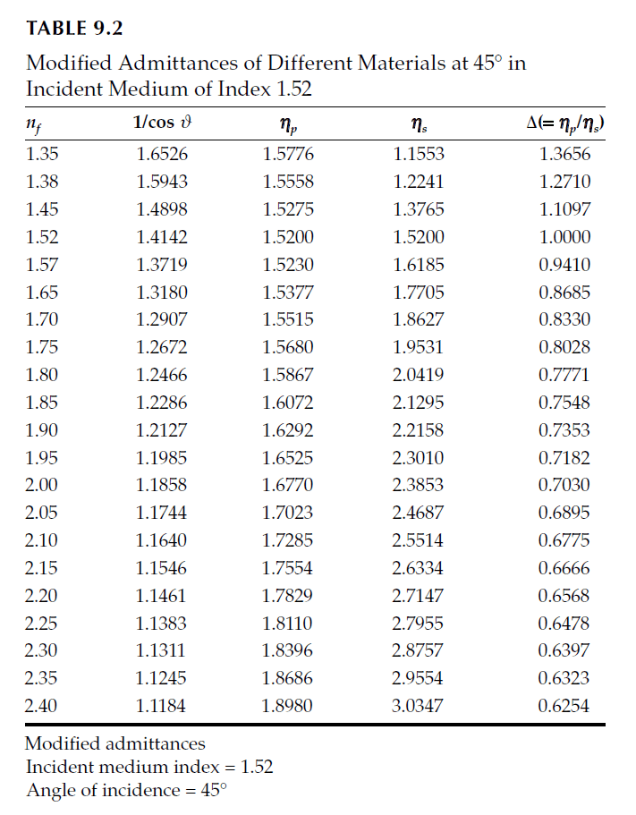
To improve reflectance at high angles of incidence, a practical approach is to use three materials—\(H\), \(L\), and \(M\)—where \(M\) has an intermediate refractive index. These materials are arranged to satisfy the condition:
\[
\Delta_H^2 \Delta_L^2 \Delta_M^2 = 2,
\tag{9.37}
\]
where \(\Delta_H = \eta_{Hp} / \eta_{Hs}\), \(\Delta_L = \eta_{Lp} / \eta_{Ls}\), and \(\Delta_M = \eta_{Mp} / \eta_{Ms}\). The multilayer structure follows the pattern:
\[
\ldots HMLMHMLMHMLM \ldots
\]
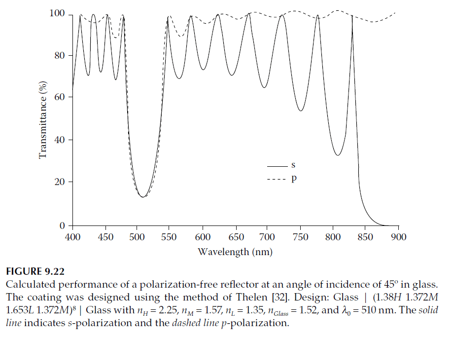
The number of layers is chosen to achieve the desired reflectance. For example, for a set of layers with refractive indices \(n_H = 2.25\), \(n_L = 1.35\), and \(n_M = 1.57\), and with \(\Delta_H = 1.3656\), \(\Delta_L = 0.6478\), and \(\Delta_M = 0.941\), the structure provides an approximate match at \(45^\circ\).
Example Performance
Using this design, the reflectance of p-polarized light increases as more layers are added. For one four-layer period, the p-admittance increases from 1.518 to 28.2 after eight periods (32 layers), resulting in a reflectance of 87%. The arrangement of \(H\), \(L\), and \(M\) layers is flexible, provided \(H\) or \(L\) layers are odd and \(M\) layers are even.
High-reflectance zones occur where the basic period is an integral number of half-waves thick. For a four-layer quarter-wave period, extra-high-reflectance zones appear at \(g = 0.5\) and \(g = 1.5\). For example, at \(g = 0.5\) (wavelength \(1020\) nm), a peak reflectance is observed.
Challenges
The performance of such coatings is limited by angular sensitivity, as the reflectance decreases significantly with deviation from the design angle. Each second pair of layers reduces the s-reflectance of the preceding pair while slightly increasing the p-reflectance. Achieving high reflectance necessitates a large number of layers, and improving angular sensitivity is challenging.
3. Edge Filters at Very High Angles of Incidence
The principles discussed in the previous section can be adapted to design edge filters for operation at high angles of incidence. However, achieving effective performance requires a large number of layers, as modest designs are insufficient.
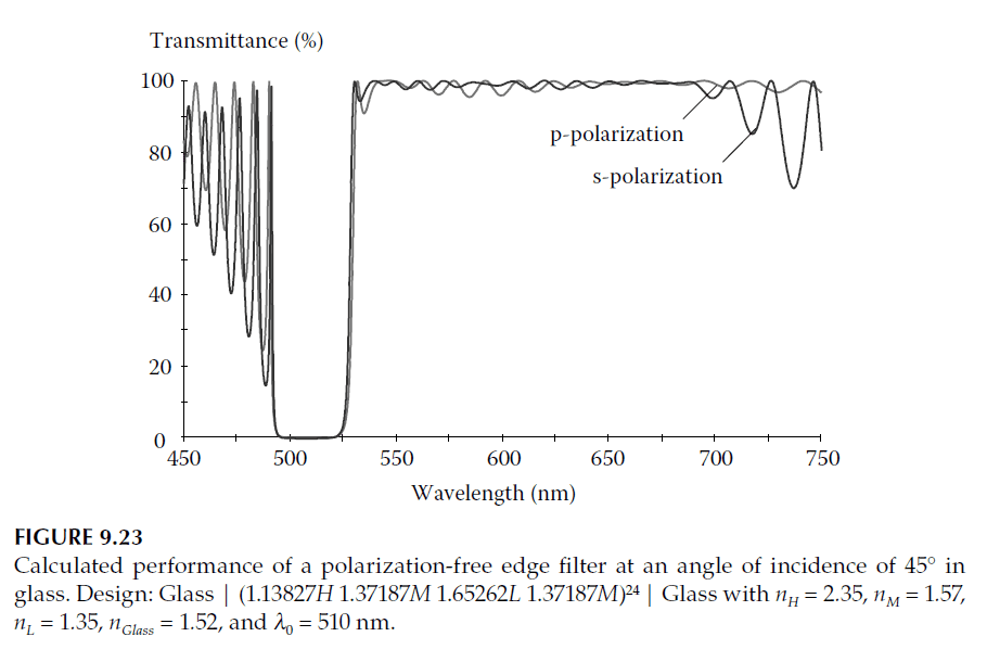
To illustrate, consider the example from Figure 9.22, where the component was initially designed as a longwave-pass filter. The design exhibits ripple on the longwave side of the peak, and the rejection is inadequate. While increasing the number of repeats to 20 significantly reduces reflectance below 0.1% across most of the rejection region, the ripple persists. To address this, the design is modified to use 24 repeats, with the outermost eight layers on either side optimized for matching.
Computer refinement is the most efficient method to finalize such a design, requiring precise adjustments to the layer thicknesses. The initial design before refinement is expressed as:
\[
\text{Glass | (1.13827H 1.37187M 1.65262L 1.37187M)}^{24} \text{ | Glass.}
\]
After refinement, the performance is significantly improved, as shown in Figure 9.23.
Design Variations
Shortwave-pass filters or filters using different materials can be designed using the same method. However, such designs are sensitive to material selection and angle of incidence, making precise calculations and refinements essential.
Challenges and Limitations
The rejection region’s width in these high-incidence edge filters is inherently limited and narrower than the split region of a conventional two-material edge filter. To meet more stringent requirements, a glass absorption filter can be added to improve performance practically. Alternatively, a second interference component with a slightly shorter wavelength may be required.