Optical coatings are applied to optical components to improve their transmission, reflection, or polarization properties. For instance, an uncoated glass component typically reflects about 4% of incident light at each surface. By applying an anti-reflection coating, this reflection can be reduced to less than 0.1%. Conversely, a highly reflective dielectric coating can increase the reflectivity to over 99.99%.
Optical coatings are made up of multiple thin layers of materials, such as oxides, metals, or rare earth materials. The performance of these coatings depends on factors like the number of layers, their thickness, and the refractive index contrast between them. This tutorial explores the principles of optical coatings, various common types, and their manufacturing processes.
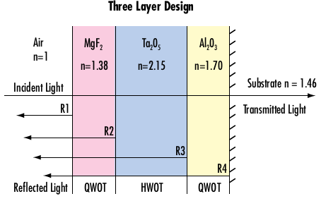
Thin film optical coatings are usually created by depositing alternating layers of dielectric and metallic materials, such as tantalum pentoxide (Ta2O5), aluminum oxide (Al2O3), or hafnium oxide (HfO2). These layers are designed to be either λ/4 (quarter-wave optical thickness, QWOT) or λ/2 (half-wave optical thickness, HWOT) of the target wavelength to optimize or reduce interference effects. The alternating high and low refractive index layers produce the interference effects necessary for the coating’s performance (see Figure 1).
Optical coatings are tailored for a specific angle of incidence and light polarization, such as s-polarization, p-polarization, or random polarization. Using the coating outside its designed angle or polarization can significantly degrade its performance. Large deviations in incidence angle and polarization may even lead to a complete loss of functionality.
Optical Coating Theory
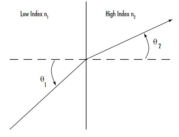
To understand optical coatings, it is essential to be familiar with the Fresnel equations for refraction and reflection. Refraction occurs when a wave changes its direction as it moves from one optical medium to another, a process described by Snell’s law of refraction:
\[\tag{1}n_1\sin\theta_1=n_2\sin\theta_2\]
n1 is the index of refraction of the incident medium, θ1 is the angle of the incident ray, n2 is the index of the refracted/reflected medium, and θ2 is the angle of the refracted/reflected ray (Figure 2).
The angle of a ray within any multilayer thin film coating composed of plane-parallel surfaces with varying refractive indices can be determined using Snell’s law. The internal angle of the ray within the film remains consistent regardless of the film’s order or position within the stack, as Snell’s law is applicable at each interface (see Figure 3):
\[\tag{2}n_1\sin\theta_1=n_2\sin\theta_2=n_3\sin\theta_3=n_4\sin\theta_4\]
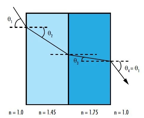
In Figure 3, the exiting ray will be parallel to the incident ray because n1 equals n4. Although optical coatings on curved surfaces do not form true plane-parallel structures due to the optic’s curvature, this approximation holds due to the thin nature of the coatings.
According to the law of reflection, the angle of the reflected ray relative to the surface normal is equal in magnitude to the angle of incidence but in the opposite direction.
\[\tag{3}\theta_1=-\theta_2\]
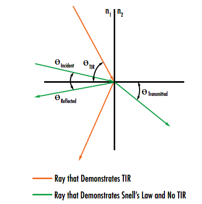
When a ray passes from a medium with a higher refractive index to one with a lower refractive index and the angle of incidence exceeds the material’s critical angle (θc), defined by the ratio of the refractive indices, total internal reflection occurs, causing the ray to be completely reflected (see Figure 4). When the incident angle matches the critical angle, the angle of refraction is 90°.
\[\tag{4}\theta_\text{C}=\sin^{-1}\left(\frac{n_2}{n_1}\right)\]
The amplitude coefficients for transmission and reflection at the interface between two optical media are governed by the Fresnel equations for transmission and reflection:
\[\tag{5}t_s=\frac{2n_1\cos\theta_1}{n_1\cos\theta_1+n_2\cos\theta_2}\]
\[\tag{6}r_s=\frac{n_1\cos\theta_1-n_2\cos\theta_2}{n_1\cos\theta_1+n_2\cos\theta_2}\]
\[\tag{7}t_p=\frac{2n_1\cos\theta_1}{n_1\cos\theta_2+n_2\cos\theta_1}\]
\[\tag{8}r_p=\frac{n_1\cos\theta_2-n_2\cos\theta_1}{n_1\cos\theta_2+n_2\cos\theta_1}\]
Where ts and tp are the amplitude transmission coefficients for s- and p-polarization, rs and rp are the amplitude reflection coefficients for s- and p-polarization, n1 and n2 are the refractive indices of the two optical media, θ1 is the incident angle, and θ2 is the transmitted or reflected angle.
At normal incidence, θ1 and θ2 are 0 making all cosine terms 1 and the amplitude coefficients the same for both polarization states. This makes intuitive sense as there is no distinction between the s- and p-polarization states at normal incidence.
Reflection takes place when light interacts with the electrons on the surface of a material. The electrons absorb and then re-emit the light, often with some energy loss. Materials that are shiny and highly reflective, such as mirrors, have a higher density of freely moving electrons, which maximizes reflection and minimizes transmission.
Optical Coating Technologies
Several physical vapor deposition (PVD) technologies are commonly used to apply optical coatings, including ion-assisted electron-beam evaporative deposition, ion beam sputtering, advanced plasma deposition, and plasma-assisted reactive magnetron sputtering (see Table 1).
Each coating technology has its own unique strengths, making it suitable for specific applications, with some overlap in their use cases. No single technology is perfect for all applications.

Ion-Assisted Electron-Beam Evaporative Deposition
Ion-assisted electron-beam (IAD e-beam) evaporative deposition is a method in which an electron gun vaporizes source materials within a vacuum chamber. The vapor condenses onto optical surfaces, forming uniform, low-stress layers with precisely designed thicknesses.
IAD e-beam coatings are known for low losses in the ultraviolet (UV) spectrum and high laser-induced damage thresholds (LIDTs) in the near-infrared (NIR) spectrum. This method also allows for greater flexibility in coating design due to its compatibility with a wide range of materials. Additionally, IAD e-beam machines can produce coatings at lower costs and handle larger chamber sizes compared to other methods.
This technique is ideal for applications where cost and flexibility take precedence over high performance. However, depending on the ion source used, coatings may have lower density, limited smoothness and reflectivity, and less consistent properties, which can make controlling layer thickness more challenging compared to ion beam or magnetron sputtering. Thus, IAD e-beam is not suitable for creating extremely low or high reflectivity coatings, such as antireflection V-coats with 99.95% transmission at 1064 nm.
Ion Beam Sputtering
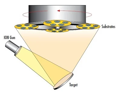
Ion beam sputtering (IBS) is a highly reliable coating technology that produces coatings with excellent optical quality and stability. In IBS, a high-energy ion beam bombards the target material, causing atoms to “sputter” off the target (Figure 5).
These atoms, with high kinetic energy (10–100 eV), form dense, hard, and smooth films on optical components. The main advantage of IBS is precise control over parameters like layer growth rate, oxidation levels, and energy input, resulting in highly repeatable coatings.
High-speed substrate rotation contributes to superior layer thickness accuracy, enabling IBS to create demanding coatings such as ultra-low loss mirrors with over 99.9% reflectivity, chirped mirrors for ultrafast lasers, and filters with sharp spectral transitions. IBS coatings are also more resistant to environmental factors like temperature and humidity.
However, IBS has drawbacks, including higher stress and increased loss in the UV spectrum. The slower deposition rates and limited chamber sizes contribute to higher costs, restricting IBS to high-performance applications.
Advanced Plasma Sputtering
Advanced plasma sputtering (APS) is a variation of IAD e-beam deposition that incorporates advanced automated processes. Instead of an ion beam, APS uses a hot cathode DC glow discharge plasma to deposit coating material. The plasma fills the chamber, releasing ions that deposit onto optical surfaces, forming smooth, dense, and hard coatings.
APS offers more stable optical properties than IAD e-beam while retaining its versatility and cost-effectiveness. APS can coat large volumes of optics at a similar price to IAD e-beam, making it suitable for applications requiring slightly higher performance.
However, APS comes with higher stress, increased loss in the UV spectrum, and requires iterative process development, which can increase costs slightly. APS and magnetron sputtering are often seen as intermediate solutions between IAD e-beam and IBS in terms of performance.
Plasma Assisted Reactive Magnetron Sputtering
Plasma assisted reactive magnetron sputtering (PARMS) is another plasma-based coating technology. Like APS, it generates a glow discharge plasma, but it is confined near the target by a magnetic field rather than filling the entire chamber. This confinement accelerates positive ions toward the target, ejecting atoms that then deposit onto optical surfaces.
PARMS operates at low chamber pressure, enhancing efficiency and reducing setup time, making it ideal for high-volume coatings. The process produces dense, hard thin-film coatings with improved stoichiometry due to the addition of reactive gases. While PARMS offers high repeatability, it is not as precise as IBS, but it has a higher throughput, balancing high performance and cost.
This makes PARMS an attractive option for applications such as manufacturing fluorescence filters, where a mix of good optical performance and high-volume production is needed.
