Designing Filters for Confocal Fluorescence Microscopes (CFMs)
When creating filters for CFMs, understanding the microscope’s unique optical configuration is crucial. Almost every CFM model has specific optical requirements, but they generally fall into two categories: those using a Nipkow-disk mechanism and those using laser beam scanning. Below is an overview of the optical specifications and requirements for each scanning type, compared to standard widefield microscopes.

Optical Quality Requirements for CFMs
Nipkow-Disk Scanning CFMs
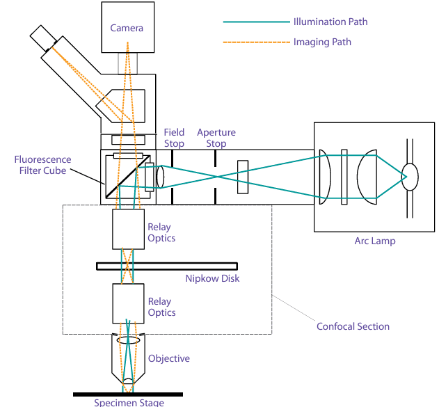
A Nipkow-disk CFM (illustrated in Figure 2) typically uses a broadband arc lamp illumination and an image detector such as a camera. This configuration is similar in principle to standard widefield microscopes, with the disk positioned in a plane conjugate to the specimen, requiring uniform illumination across the field of view, usually with Köhler illumination. This similarity means that transmitted wavefront and surface flatness requirements for excitation filters and dichroic beamsplitters are like those for widefield microscopes, as are the wedge specifications for various filters, although some adjustments might be necessary based on focal length variations across specific CFM designs.

Laser Scanning CFMs
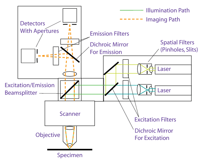
In laser scanning CFMs (illustrated in Figure 3), a laser is used for illumination, with a moving-mirror scanning mechanism and a photometric detector, such as a photomultiplier tube (PMT). These microscopes differ significantly from widefield types in two main ways:
- The pinhole or slit aperture in the illumination path is imaged directly onto the specimen, with the laser precisely focused on the sample.
- The image is generated by matching the train of electrical signals from the detector with the laser’s position on the specimen, similar to television image formation.

Here, the excitation filters and beamsplitters need a higher optical quality and registration than in other types due to the laser’s need for undistorted focus at the specimen plane and minimal angular deviation. Typically, systems require transmitted wavefront distortion and surface flatness around one wave per inch for excitation filters and beamsplitters, with wedge specifications as tight as one arc-minute or less to ensure minimal alignment adjustments when changing filters. Additionally, in the imaging path, any filters or beamsplitters situated between the objective and detection aperture must meet imaging quality standards.
Spectral Requirements for CFMs
Nipkow-Disk Scanning CFMs
This configuration’s light source and detection system resemble standard widefield EFMs. Thus, the spectral requirements are similar, except for reduced signal intensity and added optical elements, which increase reflections and scattering. Here, excitation and emission filters must exhibit very low cross-talk and extra care must be taken to control pinhole quality.
Laser Scanning CFMs
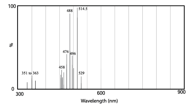
Filters and beamsplitters in laser scanning CFMs are specifically designed for the laser type in use, often a solid-state or diode-pumped solid-state (DPSS) laser, with various wavelengths available across the visible spectrum. When designing filters for laser-based CFMs, key considerations include:
- Excitation Filters – They should block the entire laser output spectrum. For traditional lasers, filters blocking up to 800 nm are generally sufficient, while DPSS lasers may require blocking in the near-infrared (NIR) range, especially around 1064 nm, to match the detector’s response range. Laser excitation filters should ideally attenuate light by reflection to reduce thermal load, particularly with UV excitation for argon-ion lasers.
- Dichroic Beamsplitters – Since most lasers are polarized, understanding the laser’s polarization conditions is valuable. Optimizing beamsplitters to align with the laser’s orientation enhances performance; for example, a beamsplitter designed for the S-plane orientation of a 488 nm argon-ion laser line can maximize throughput. Fluorescent emissions are mostly unpolarized even when excitation light is polarized, so beamsplitters should efficiently transmit emissions across both polarization planes.
- Emission Filters – On the short-wavelength side, emission filters must block all laser lines associated with the filter. For applications involving multiple probes, blocking on the long-wavelength side enhances probe signal selectivity. The blocking range generally aligns with the detector range, which may be as short as 700 nm for some PMTs (as shown in Figure 1).
