The phase dispersion filter predates the development of narrowband filters for telecommunications applications and represents an innovative approach to overcoming the manufacturing difficulties associated with conventional narrowband filters.
Historically, these conventional filters became increasingly challenging to produce as their half-widths decreased below approximately 0.3% of the peak wavelength. Higher-order cavities were explored but proved ineffective when the cavity order exceeded four, primarily due to increased surface roughness and other limitations, such as moisture-induced drifts, which were not fully understood at the time.
Although the phase dispersion filter did not ultimately solve the narrowband filter problem, its design philosophy offers valuable insights.
Concept and Design Philosophy
Baumeister and Jenkins proposed the phase dispersion filter to utilize the phase dispersion effect rather than high reflectance for achieving narrow bandwidth. These filters are built as single-cavity all-dielectric filters but replace conventional quarter-wave reflectors with staggered multilayer reflectors. The rapid phase change induced by staggered multilayers reduces sensitivity to cavity thickness errors, improving bandwidth stability and peak positioning.
Despite promising results, practical implementations of these filters fell short of theoretical expectations. Further studies, such as those by Giacomo et al., investigated how layer thickness errors and uniformity influenced filter performance. These studies aimed to minimize sensitivity to errors, optimizing bandwidth and layer “roughness.”
Key Findings on Error Sensitivity
1. Peak Shift Sensitivity:
The peak wavelength (\(\nu\)) of an all-dielectric multilayer filter depends on the phase condition:
\[
\phi_a + \phi_b – \delta = m\pi,
\]
where \(\phi_a\) and \(\phi_b\) represent phase changes from reflectors, and \(\delta\) corresponds to the cavity layer’s phase shift.
2. Impact of Thickness Errors:
Changes in the layer thickness (\(d_i\)) and cavity thickness (\(d_c\)) shift the peak wavelength, expressed as:
\[
\Delta \nu = -\frac{\partial (\phi_a + \phi_b – 2\delta)}{\partial \nu}.
\]
3. Error Minimization:
By assuming random thickness errors proportional to \(\sqrt{d}\), it was shown that a filter’s mean square thickness deviations directly impact its resolution (\(R\)):
\[
R = \frac{T}{k^{1/2}},
\]
where \(T\) is the total filter thickness and \(k\) represents the proportionality constant for error magnitude.
Comparison of Reflectors
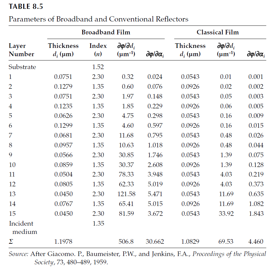
Giacomo et al. compared staggered multilayers to conventional quarter-wave stacks using 15-layer broadband and conventional reflectors. Their findings showed that staggered multilayers exhibited better compliance with error minimization criteria, achieving a lower sensitivity (\(\beta\)):
– Broadband Reflector: \(\beta = 1.023k\),
– Quarter-Wave Reflector: \(\beta = 1.289k\),
– Theoretical Minimum: \(\beta = 0.652k\).
While the phase dispersion filter outperformed classic designs, it fell short of achieving the theoretical limit.
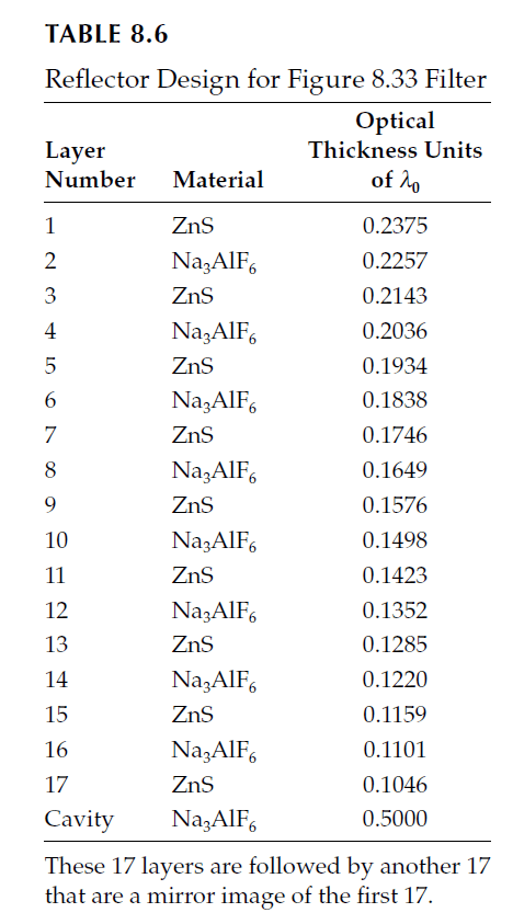
Experimental Results
Ritchie further demonstrated the phase dispersion filter’s performance using zinc sulfide and cryolite on a glass substrate. The filter design, shown in Table 8.6, yielded the following experimental results at 1.348 μm:
| Peak Wavelength (μm) | Experimental Bandwidth (nm) | Theoretical Bandwidth (nm) |
|---|
| 1.047 | 3.0 | 0.8 |
| 1.159 | 2.5 | 1.7 |
| 1.282 | 4.0 | 4.6 |
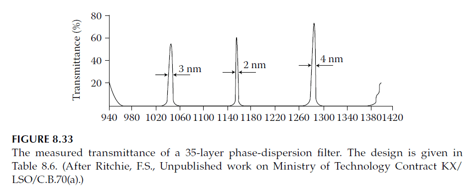
These results illustrate the challenges in achieving theoretical performance while highlighting the improved resolution compared to classic filters.
Conclusion
The phase dispersion filter demonstrates a unique approach to narrowband filter design, emphasizing reduced sensitivity to manufacturing errors through phase dispersion properties. While it did not replace conventional designs, it provided valuable insights into error mitigation and paved the way for advancements in thin-film technology.