1. The Brewster Angle Polarizing Beam Splitter
This type of beam splitter was first constructed by Mary Banning at the request of S. M. MacNeille, the inventor of the device, which is frequently known as a MacNeille polarizer.
The principle of the device is that it is always possible to find an angle of incidence so that the Brewster condition for an interface between two materials of differing refractive indices is satisfied. When this condition is met, the reflectance for the p-plane of polarization vanishes. The s-polarized light is partially reflected and transmitted. To increase the s-reflectance, while retaining the p-transmittance at or near unity, the two materials may be made into a multilayer reflecting stack. The layer thickness should correspond to quarter-wave optical thicknesses at the appropriate angle of incidence.
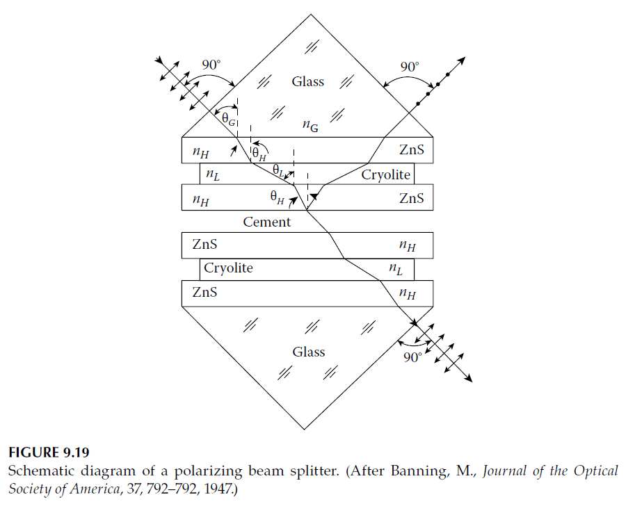
When the Brewster angle for typical thin-film materials is calculated, it is found to be greater than \(90^\circ\) when referred to air as the incident medium. In other words, the angle is beyond grazing incidence for the materials. This presents a problem that is solved by building the multilayer filter into a glass prism, allowing the light to be incident on the multilayer at an angle greater than what is possible with air as the incident medium. The arrangement is shown in Figure 9.19.
The calculation of the design is straightforward. Consider two materials with refractive indices \(n_H\) and \(n_L\) (where \(H\) and \(L\) refer to high and low refractive indices, respectively). The Brewster condition is satisfied when the angle of incidence satisfies the relationship:
\[
n_H \cos \theta_H = n_L \cos \theta_L
\tag{9.16}
\]
where:
\[
n_G \sin \theta_G = n_H \sin \theta_H = n_L \sin \theta_L
\tag{9.17}
\]
Here, \(G\) refers to the glass of the prism. These equations can be solved for \(\theta_H\) as:
\[
\sin^2 \theta_H = \frac{n_L^2}{n_H^2 + n_L^2}
\tag{9.18}
\]
This result is often written as:
\[
\tan^2 \theta_H = \frac{n_L^2}{n_H^2}.
\]
Given the layer indices, there are two approaches to designing the system. Either the refractive index of the glass is chosen and the necessary prism angle is calculated, or the prism angle (e.g., \(45^\circ\)) is fixed and the required refractive index of the glass is determined. Mary Banning adopted the latter approach.
Assuming \(\theta_G = 45^\circ\), and using Equations (9.17) and (9.18), we obtain:
\[
n_G^2 = n_H^2 + n_L^2
\tag{9.19}
\]
If \(n_G\) is fixed, the equations yield:
\[
\sin^2 \theta_G = \frac{n_H^2 + n_L^2}{n_G^2}.
\tag{9.20}
\]
Banning used zinc sulfide with an index of 2.30 and cryolite evaporated at a pressure of \(10^{-3}\) Torr (0.133 Pa) to achieve a porous layer index around 1.25. For these materials, a glass index of 1.55 was needed to achieve a prism angle of \(45^\circ\). With cryolite having a more typical index of 1.35 and zinc sulfide at 2.35, the required glass index would be 1.66. Alternatively, for glass with an index of 1.52, the angle of incidence using the latter pair of materials would be \(50.5^\circ\).
The degree of polarization at the center wavelength can also be calculated using:
\[
R_q = \frac{\eta_G – \eta_H}{\eta_G + \eta_H} \cdot \frac{\eta_G – \eta_L}{\eta_G + \eta_L},
\tag{9.21}
\]
where \(q\) is the number of layers, assumed to be odd. For s-waves:
\[
\eta_G = \frac{n_G}{\cos \theta_G}, \quad \eta_H = \frac{n_H}{\cos \theta_H}, \quad \eta_L = \frac{n_L}{\cos \theta_L}.
\]
For p-waves, the expressions are modified as:
\[
\eta_G = \frac{\cos \theta_G}{n_G}, \quad \eta_H = \frac{\cos \theta_H}{n_H}, \quad \eta_L = \frac{\cos \theta_L}{n_L}.
\]
For p-waves, the reflectance simplifies under the imposed conditions to:
\[
R_p = \left( \frac{n_H^2 \cos \theta_H – n_L^2 \cos \theta_L}{n_H^2 \cos \theta_H + n_L^2 \cos \theta_L} \right)^2.
\tag{9.22}
\]
For s-waves, the reflectance is given by:
\[
R_s = \left( \frac{n_H^2 – n_L^2}{n_H^2 + n_L^2} \right)^q.
\tag{9.23}
\]
Polarization in Transmission and Reflection
The degree of polarization in transmission is:
\[
P_T = \frac{T_p – T_s}{T_p + T_s},
\tag{9.25}
\]
and in reflection:
\[
P_R = \frac{R_s – R_p}{R_s + R_p}.
\tag{9.26}
\]
Generally, for a small number of layers, polarization in reflection is superior to transmission, but for a large number of layers, transmission performance improves beyond reflection.
The construction of the beam splitter is similar to the cube beam splitter discussed in previous tutorials. Banning’s original coating consisted of three layers due to practical constraints at the time. Nowadays, coatings with 21 or more layers are easily deposited, often on a single prism, with the untreated prism cemented to it.
This polarizing beam splitter offers a wide spectral range and a large physical aperture, outperforming other types like the pile-of-plates polarizer. However, it has a limited angular field, especially near the design angle. Away from the design angle, residual p-polarization reflectance peaks appear at the center of the range, reducing performance. Skew rays also affect polarization by introducing leakage from the p-polarized component. These limitations can be mitigated by using higher incidence angles, as described by Li and Dobrowolski.
2. Plate Polarizer
The width of the high-reflectance zone of a quarter-wave stack depends on the ratio of the admittances of the two materials involved. This ratio varies with the angle of incidence and differs for s- and p-polarizations. Recall the relationships:
\[
\eta_s = n \cos \theta, \quad \eta_p = \frac{n}{\cos \theta}.
\]
Thus, for s-polarization:
\[
\frac{\eta_{Hs}}{\eta_{Ls}} = \frac{\cos \theta_H}{\cos \theta_L},
\]
and for p-polarization:
\[
\frac{\eta_{Hp}}{\eta_{Lp}} = \frac{\cos \theta_L}{\cos \theta_H}.
\]
From these, we can derive:
\[
\frac{\eta_{Hs}/\eta_{Ls}}{\eta_{Hp}/\eta_{Lp}} = \frac{\cos^2 \theta_H}{\cos^2 \theta_L}.
\tag{9.27}
\]
The factor \(\cos^2 \theta_H / \cos^2 \theta_L\) is always less than unity, implying that the high-reflectance zone for p-polarized light is narrower than for s-polarized light. Consequently, within the region outside the p-polarized but inside the s-polarized high-reflectance zone, the transmittance is low for s-polarized light but high for p-polarized light. This property enables the component to act as a polarizer.
However, the region is relatively narrow, making this type of polarizer unsuitable for broad wavelength ranges. Nevertheless, for single-wavelength applications, such as a laser line, it can be highly effective.
To finalize the design, it is necessary to minimize the ripple in the p-polarized light’s transmission. This can be achieved using various techniques described in previous tutorials. Among these, Thelen’s shifted-period method is particularly useful, as performance near the edge of the passband is critical. In modern practice, computer-based refinement of the outermost layers of the coating is more common.
Typically, the plate polarizer is designed as a longwave-pass filter, as this requires thinner layers and less material than a shortwave-pass filter. The rear surface of the component should be coated with an antireflection coating for p-polarized light, though this can be omitted if the component is used at the Brewster angle.
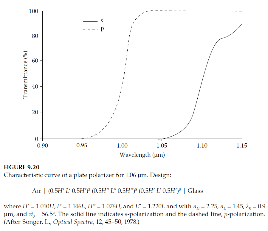
A design for such a polarizer is described by Songer, who provides the configuration shown in Figure 9.20. Plate polarizers are preferred over prism-based polarizers, such as the MacNeille type, for high-power applications.
Virtually any coating with a sharp edge between transmission and reflection can function as a polarizer. Narrowband filters have been suggested as advantageous alternatives to simple quarter-wave stacks for plate polarizer coatings. This is because narrowband filters simplify the monitoring process during deposition.
3. Cube Polarizers
One of the key advantages of a polarizer immersed in a prism is that the effective angle of incidence can be significantly higher than it would be if the incident medium were air. This higher angle enhances the polarization splitting, resulting in broader regions with a high degree of polarization compared to designs where air is the incident medium.
Even when the Brewster angle condition cannot be fully achieved, an immersed design still provides advantages, particularly when the incident power is not excessively high. The immersion enhances the optical performance of the polarizer by reducing angular constraints and improving the separation of polarization states.
For detailed information and design considerations for such polarizers, Netterfield has provided a thorough analysis in his paper, which is recommended for further study.