In many optical applications, the polarization state of a light ray is crucial. Optical surfaces, with or without coatings, can modify the polarization properties, making it necessary to understand and measure these changes. Such measurements are valuable for surface and coating characterization, and specially designed coatings can deliberately manipulate polarization. Before quantifying these effects, we define key terms and conventions.
1. The Ellipsometric Parameters and Relative Retardation
We consider a completely polarized beam with two orthogonal electric field components that are completely coherent. The ellipsometric parameters \(\psi\) (psi) and \(\Delta\) (Delta) are defined as:
\[
\tan \psi = \frac{E_x}{E_y} \quad \text{and} \quad \Delta = \phi_x – \phi_y \tag{9.41}
\]
– \(\Delta\) is also called the relative retardation or retardance.
– These parameters depend on the choice of reference axes.
To avoid confusion, note that this \(\Delta\) is distinct from the one used in Equations 9.36 and following sections.
Conventions for Reflection and Transmission
For reflection at an optical surface, it is convenient to align the reference axes with the p- and s-polarization directions. In this case:
\[
\tan \psi = \frac{\rho_p}{\rho_s} \quad \text{or} \quad \frac{\tau_p}{\tau_s} \quad \text{and} \quad \Delta = \phi_p – \phi_s \tag{9.42}
\]
Here:
– \(\rho\) represents the reflection coefficients.
– \(\tau\) represents the transmission coefficients.
Reference Axis Handedness
A complication arises due to the handedness of the reference axes relative to the propagation direction. In thin film optics, the convention is:
– Right-handed for incidence and transmission.
– Left-handed for reflection.
To simplify matters, the ellipsometric convention flips the p-direction for the reflected ray. At normal incidence, this adjustment removes the problem of orientational dependence, as no plane of incidence exists.
Modified Definition of \(\Delta\)
To ensure consistency, the definition of \(\Delta\) becomes:
– In transmission:
\[
\Delta = \phi_p – \phi_s \tag{9.43}
\]
– In reflection:
\[
\Delta = \phi_s – \phi_p \pm \pi
\]
Behavior at Normal Incidence
At normal incidence, circularly polarized light reflected from a surface remains circularly polarized but changes its handedness. This corresponds to a relative retardance (\(\Delta\)) of \(\pi\) (180°), consistent with Expression 9.43. Under these conditions:
– \(\psi\) equals 45°.
– \(\Delta\) equals 180° (or \(\pi\)).
Any pair of orthogonal axes forming a right-handed set with the direction of propagation can be used without affecting the values of \(\psi\) and \(\Delta\).
Retarders and Half-Wave Plates
A reflection at normal incidence is sometimes described as a half-wave plate or half-wave retarder. However, this terminology is misleading because it does not behave like a conventional half-wave retarder. For example, it cannot rotate the plane of polarization.
We will discuss the properties and behavior of retarders in greater detail in the following sections.
2. Series of Coated Surfaces
Understanding the absolute phase of a light ray requires precise knowledge of the path length traversed by the ray. In most optical systems, this path length is neither known nor constant with the required precision. However, for analyzing the effects on light polarization, the absolute phase is irrelevant; only the phase difference between reference components matters.
Unless there is optical activity (which introduces a differential phase shift between components), we typically ignore phase changes from the passage between surfaces and consider only the changes occurring at the surfaces. Since the phase difference is what matters, we use Δ to describe it. If individual phases for each polarization are needed, the net Δ can be assigned to the final p-polarized component, with the s-polarized phase set to zero.
Combining Multiple Surfaces
At oblique incidence, \(\psi\) and \(\Delta\) are defined relative to the plane of incidence. If the plane of incidence remains consistent for all subsequent reflections or transmissions, combining the effects of multiple surfaces is straightforward. Since the p- and s-polarization directions are independent, the combined reflection coefficients (\(\rho\)) can be written as:
\[
\rho_p = \rho_{p1} \cdot \rho_{p2} \cdot \rho_{p3} \cdots \quad \text{and} \quad \rho_s = \rho_{s1} \cdot \rho_{s2} \cdot \rho_{s3} \cdots \tag{9.44}
\]
In these equations:
– Each \(\rho\) can be replaced by \(\tau\) for transmissions.
– The ellipsometric convention for \(\rho_p\) must be used.
The combined ellipsometric parameters become:
\[
\tan \psi = \tan \psi_1 \cdot \tan \psi_2 \cdots \quad \text{and} \quad \Delta = \Delta_1 + \Delta_2 + \Delta_3 + \cdots \tag{9.45}
\]
Non-Coincident Planes of Incidence
If the planes of incidence are not coincident, the situation becomes significantly more complicated, making \(\psi\) and \(\Delta\) less useful. Since each plane of incidence contains the ray, the problem involves rotating each plane of incidence around the ray direction. This can be handled using Jones matrices for rotation.
Jones Matrix Approach
For the Jones matrix representation, the reference directions for the input electric field are typically chosen as the p- and s-directions of the beam as it exits the previous element. Let \(\vartheta\) represent the angle of rotation of the new p- and s-directions around the propagation axis. The transformation can be expressed as:
\[
\begin{bmatrix}
E’_p \\ E’_s
\end{bmatrix}
=
\begin{bmatrix}
\cos \vartheta & \sin \vartheta \\
-\sin \vartheta & \cos \vartheta
\end{bmatrix}
\begin{bmatrix}
\rho_p & 0 \\
0 & \rho_s
\end{bmatrix}
\begin{bmatrix}
E_p \\ E_s
\end{bmatrix} \tag{9.46}
\]
Here:
– \(E’_p\) and \(E’_s\) are the electric field components in the rotated frame.
– The ellipsometric convention applies to \(\rho_p\).
Alternative Vector Approach
While the Jones matrix approach works, it requires careful tracking of reference directions and rotations, which can be cumbersome—especially when dealing with transmissions. An alternative approach is to use three-dimensional reference axes for all calculations. By defining the directions of the:
– Surface normals,
– Coating properties, and
– Whether reflection or transmission occurs,
everything can be referred to a common coordinate system. Vector analysis provides a straightforward framework for such calculations, making it easier to handle complex scenarios.
Key Consideration
The most important requirement for handling these calculations is a clear and organized approach. Keeping track of rotations, reference directions, and material properties is essential for accurate results.
3. Retarders
Phase retarders introduce a relative phase shift between two orthogonal planes of polarization and are characterized by their relative retardance, Δ. Most commonly, retarders are made of birefringent materials with different refractive indices for each polarization. If the indices are \(n_a\) and \(n_b\), the relative phase shift introduced by the plate is:
\[
\Delta = \frac{2\pi (n_a – n_b) d}{\lambda}
\]
where:
– \(d\) is the physical thickness of the plate,
– \(\lambda\) is the wavelength of light.
Typically, the direction corresponding to the electric field for the lower refractive index is called the fast axis. This axis helps determine the sense of the relative phase shift, although the terminology is not always consistent.
Advantages and Limitations of Birefringent Retarders
Birefringent retarders are straightforward components that preserve the direction of the light beam, which makes them easy to use. However, they have limitations:
1. Size and Cost: Large retarders can be prohibitively expensive or impractical.
2. Reflection Loss: The surfaces introduce reflection losses, which often require antireflection coatings.
3. Wavelength Dependence: The retardance depends on \(1/\lambda\), meaning the phase shift varies with wavelength. To overcome this, achromatic retarders are typically made from two or more different materials.
Thin-film retarders can address some of these limitations.
Thin-Film Retarders
Isotropic materials exhibit no polarization-sensitive effects at normal incidence. However, when tilted, they display differences in their properties for s- and p-polarized light, which forms the basis for their application as retarders.
1. Phase Thickness: The phase thickness of a thin film is the same for both s- and p-polarizations.
2. Transmission Devices: For a retarder operating in transmission, the reflectance should be low, ensuring the light transmits with minimal phase shift differences between polarizations. However, significant differences typically arise only in narrowband filters, where light is stored in cavities. Such filters are more suitable as polarizers than as retarders.
Reflecting thin-film retarders are the most useful type because they can manipulate polarization efficiently. Since polarization can be perturbed by differences in reflectance, even without relative phase changes, the reflectances for s- and p-polarizations should be made as equal as possible. This usually requires maximizing the reflectance.
Conventions and Polarization Effects
In designing thin-film retarders, we focus on tilted reflectances and their effect on polarization. It is convenient to use the ellipsometric parameters ψ and Δ (defined in Equations 9.42 and 9.43) to describe the performance:
– ψ: Measures the reflectance ratio between p- and s-polarizations.
– Δ: Describes the relative retardance or phase shift.
Ideally, we design retarders to have no influence on polarization due to reflectance differences, which implies that:
\[
\psi = 45^\circ
\]
Implications of ψ ≠ 45°
If \(\psi\) differs from \(45^\circ\), there are practical implications for the polarization state:
1. Linearly Polarized Light:
– Consider linearly polarized light incident at \(45^\circ\) to the plane of incidence.
– This gives equal amplitudes for both s- and p-polarizations.
– Upon reflection, characterized by \(\psi\), the new plane of polarization will rotate to angle \(\psi\) relative to the s-direction.
– Errors in \(\psi\) result in a rotation of the polarization plane.
The largest rotation occurs when the incident polarization direction is \(45^\circ\) to the plane of incidence. The rotation angle is:
\[
\varepsilon = 45^\circ – \psi
\]
2. Circularly Polarized Light:
Circularly polarized light will become slightly elliptical due to this rotation. The effect is equivalent to the original linearly polarized light used to generate the circular polarization being rotated through \(\varepsilon\) away from the ideal \(45^\circ\) alignment with the fast axis of a quarter-wave plate.
Summary
We use ψ as a key characteristic to evaluate the performance of thin-film retarders. By designing the coatings such that \(\psi\) remains close to \(45^\circ\), we minimize errors in polarization rotation and maintain the desired relative phase shift (\(\Delta\)) for efficient operation.
4. Simple Retarders
The simplest retarders are not strictly thin-film systems. Below the critical angle, the ellipsometric parameters \(\psi\) and \(\Delta\) associated with reflection at a dielectric surface are of limited interest:
– \(\psi\): Varies from \(45^\circ\) to \(0^\circ\) and back to \(45^\circ\) as the angle of incidence \(\vartheta\) increases.
– \(\Delta\): Starts at \(180^\circ\) and transitions to zero as the angle of incidence approaches grazing incidence or the critical angle, whichever occurs first.
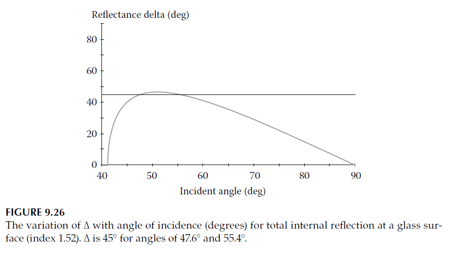
Behavior Beyond the Critical Angle
Beyond the critical angle (when the incident medium has a higher refractive index than the emergent medium), the behavior changes:
– \(\psi\): Remains fixed at \(45^\circ\).
– \(\Delta\): Rises from zero to a maximum and then falls back to zero.
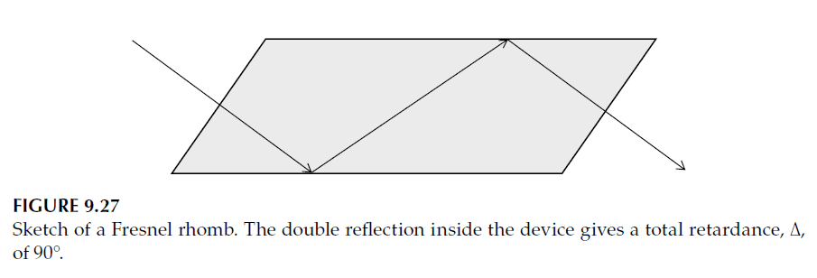
This behavior is shown in Figure 9.26. There are two specific angles of incidence at which the retardance equals \(45^\circ\). By combining two such reflections, a total relative phase shift (\(\Delta\)) of 90° (quarter-wave retardance) is achieved. Devices that use this principle are known as Fresnel rhombs (see Figure 9.27).
Metallic Layers as Retarders
A high-performance metallic layer can act as a simple retarder. The admittance of such a metal layer at oblique incidence is approximated by:
\[
\eta_s = \frac{(n – ik)}{\cos \vartheta_0}, \quad \eta_p = (n – ik)\cos \vartheta_0
\]
Here:
– \(n – ik\) represents the complex refractive index of the metal.
– \(\vartheta_0\) is the angle of incidence.
As the angle of incidence increases:
– s-admittance (\(\eta_s\)) moves away from the origin.
– p-admittance (\(\eta_p\)) moves toward the origin.
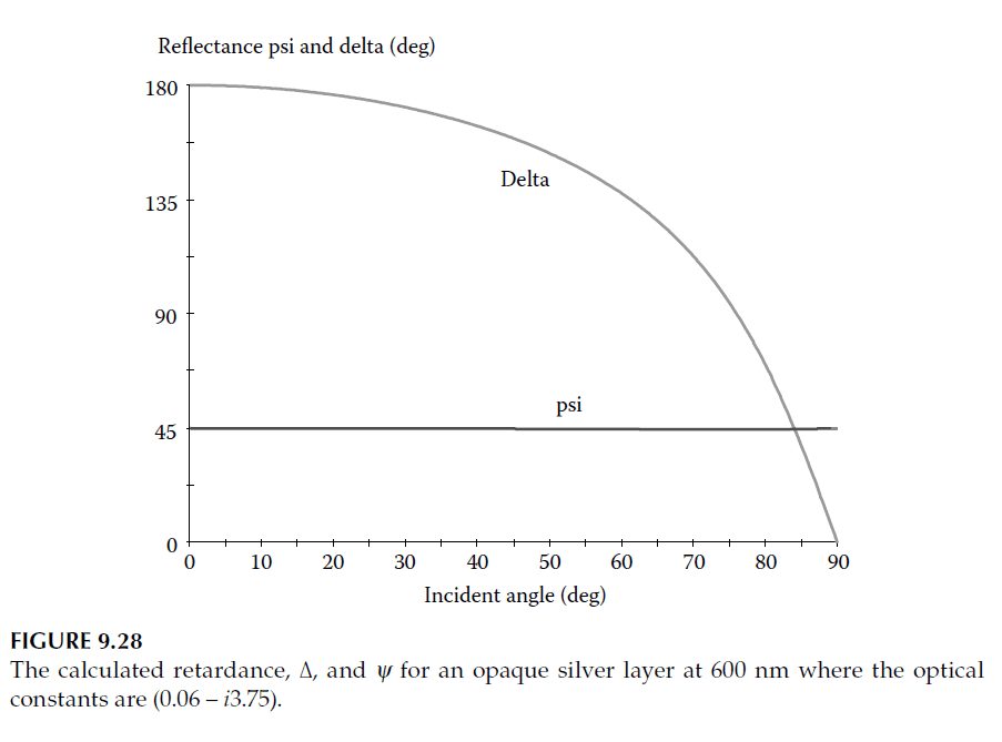
At normal incidence, the phase shifts for s- and p-polarizations are equal. As the angle of incidence increases:
– The p-phase shift reduces to zero at grazing incidence.
– The s-phase shift increases to \(180^\circ\) at grazing incidence.
The relative retardance (\(\Delta\)) is thus \(180^\circ\) at normal incidence and falls to zero at grazing incidence (including an additional \(180^\circ\) phase shift). The behavior of silver at 600 nm is shown in Figure 9.28, where \(\psi\) remains close to \(45^\circ\), dropping slightly near the pseudo-Brewster angle.
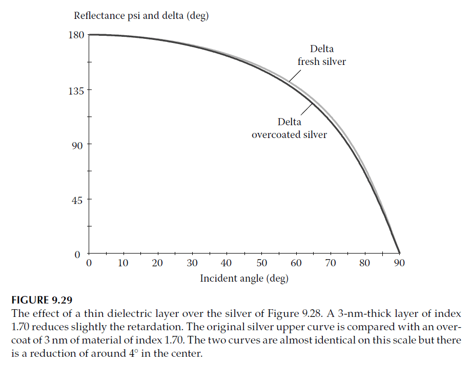
Effect of Thin Dielectric Overcoats
A thin dielectric overcoat (e.g., a tarnish layer) slightly reduces the retardance. For example:
– A 3 nm dielectric layer with \(n = 1.70\) causes the p-polarization locus to drop faster than the s-polarization locus.
– This results in a reduction of \(\Delta\) by approximately 4° at its maximum.
The retardance also varies with wavelength and angle of incidence, but such simple retarders remain useful shortly after deposition in controlled conditions.
Fresnel Rhombs and Thin-Film Coatings
The Fresnel rhomb is an example of a simple retarder that achieves nearly achromatic performance. However:
1. Dispersion of Glass: Causes the retardance to increase as the wavelength decreases.
2. Sensitivity to Angle of Incidence: Performance is affected by small changes in incidence angle.
These issues can be mitigated with thin-film coatings on the rhomb surfaces. For example:
– King developed Fresnel rhombs with phase retardation variations of less than 0.4° over the wavelength range 330–600 nm.
– These devices used hard crown glass coated with a 20 nm magnesium fluoride film on one surface.
Thin-Film Retarders at Oblique Incidence
To understand how thin films affect retardance, consider a prism hypotenuse with:
– Glass (\(n = 1.52\)) as the prism material.
– Air as the external medium.
– An incidence angle of \(45^\circ\) (beyond the critical angle).
When a dielectric thin film is added to the hypotenuse at oblique incidence, the following occurs:
1. High-Index Film:
– The s-admittance increases, while the p-admittance decreases.
– The retardance (\(\Delta\)) changes as the film thickness varies:
– Eighth-wave thickness: Introduces phase shifts on reflection.
– Quarter-wave thickness: Brings s- and p-admittances in step, producing a retardance of \(180^\circ\).
– Further phase accumulation causes periodic changes in \(\Delta\).
2. Low-Index Film:
– The p-admittance increases, while the s-admittance decreases.
– The retardance variation behaves oppositely to the high-index film but exhibits tighter cycles due to a larger \(\cos \vartheta\) term.
The extent of polarization splitting (shown in Figure 9.29) indicates the maximum attainable retardance.
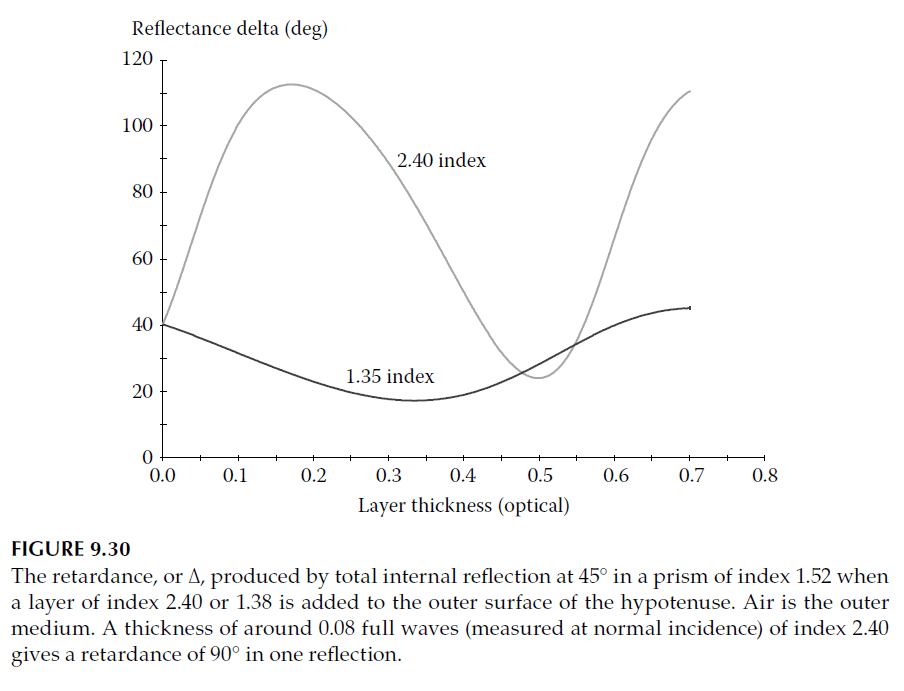
High- and Low-Index Film Performance
The calculated retardance behavior of a high-index film (\(n = 2.40\)) and a low-index film (\(n = 1.38\)) is shown in Figure 9.30. A thin layer of high admittance (around 0.08 full wave for \(n = 2.40\)) can transform the retardance to 90° in just one reflection at \(45^\circ\) incidence.
Summary
– Simple retarders, such as Fresnel rhombs and high-performance metal layers, achieve phase shifts using reflection at oblique incidence.
– Thin dielectric films modify retardance, with their effect depending on the film index and thickness.
– Thin-film coatings enhance performance, achieving improved achromaticity and reduced sensitivity to angle of incidence.
5. Multilayer Retarders at One Wavelength
Reflecting coatings designed to introduce specific phase retardances between s- and p-polarizations have been widely used in various applications. A notable example is in high-power laser resonators, where coatings are required to introduce a 90° phase shift between s- and p-polarizations at an incidence angle of 45°. These coatings are typically designed for infrared wavelengths and often consist of silver films with multilayer dielectric overcoats.
Historical Context and Design Approaches
The first designs were introduced by Southwell using a computer synthesis technique. Apfel later developed an analytical approach, which is the basis of the method described here.
The principle behind these coatings is straightforward:
– For a system with reflectance of unity, adding a dielectric layer will not affect the reflectance but will alter the phase change on reflection.
– At oblique incidence, the phase change introduced differs for the s- and p-polarizations.
– By adding layers in the correct sequence, any desired phase difference between the polarizations can be achieved for a specific wavelength and angle of incidence.
While silver layers are commonly used due to their high reflectance in the infrared, dielectric stacks can also serve as the starting reflector, albeit with more layers.
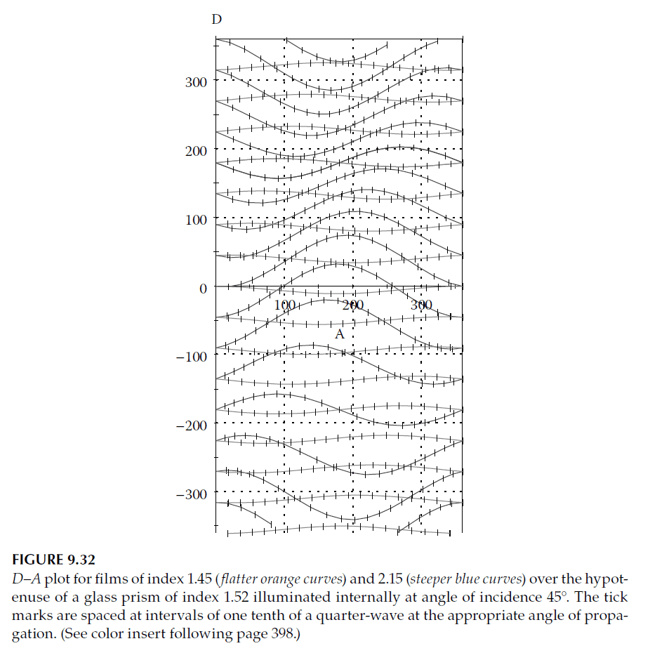
Apfel’s Method
Apfel’s method involves plotting the phase retardance (D) against the average phase shift (A) as a function of the thickness of an added dielectric layer.
Key points include:
1. Starting Conditions:
– The reflector has unity reflectance with an imaginary admittance:
\[
\rho_p = \frac{y_0 – i \beta}{y_0 + i \beta} = e^{i \phi_p}, \quad \rho_s = \frac{y_0 + i \beta}{y_0 – i \beta} = e^{i \phi_s}
\]
– The phase shifts are:
\[
\tan\left(\frac{\phi_p}{2}\right) = -\frac{\beta}{y_0}, \quad \tan\left(\frac{\phi_s}{2}\right) = \frac{\beta}{y_0}
\]
These values are numerically equal but have opposite signs. They can be represented as \(\pm \xi\), where:
\[
\beta = -y_0 \tan \xi
\]
2. Adding a Dielectric Layer:
– For a layer with admittance \(\eta_1\) and phase thickness \(\delta_1\), the new admittance is:
\[
\eta_1 = \frac{\cos \delta_1 + i (\beta / \eta_1) \sin \delta_1}{i \eta_1 \sin \delta_1 + \beta \cos \delta_1}
\]
– The phase shifts for s- and p-polarizations are given by:
\[
\tan\left(\frac{\phi_p}{2}\right) = \frac{\eta_1 \delta_1 – \beta \sin \delta_1}{y_0 (\beta / \eta_1) – \cos \delta_1}
\]
\[
\tan\left(\frac{\phi_s}{2}\right) = \frac{-\eta_1 \delta_1 – \beta \sin \delta_1}{y_0 (\beta / \eta_1) + \cos \delta_1}
\]
Plotting D–A Curves
The D–A curve is a plot of the difference in phase (D) versus the average phase (A), calculated from the above expressions:
– Start with \(D = \Delta = 2\xi \pm 180^\circ\) and \(A = 0\).
– Different values of \(\xi\) produce a family of curves.
– To avoid ambiguity, D is allowed to range from \(-360^\circ\) to \(+360^\circ\).
As the thickness of the layer increases, the curves shift accordingly, with thickness often marked along the curve. For example:
– Movement to the left corresponds to increasing thickness.
– Curves reappear cyclically on opposite edges of the plot (left-to-right and top-to-bottom).
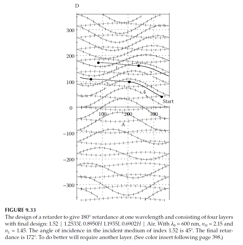
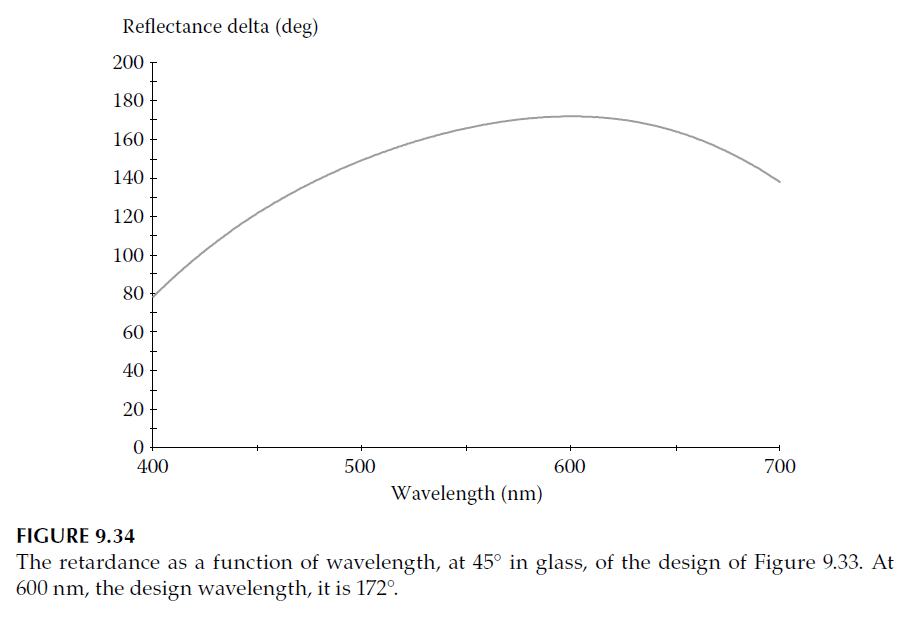
Design Example
Figure 9.32 illustrates the design of a phase retarder with a target retardance of 180°:
1. Starting Point: A glass–air interface beyond the critical angle.
2. Layer Sequence: Layers are added sequentially along their respective D–A curves.
3. Final Retardance: For four layers, the final retardance is 172°, which is near-optimal. Adding another layer can improve performance further.
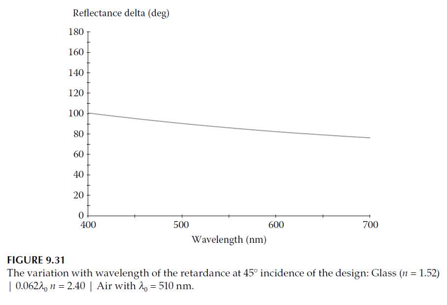
The performance across wavelengths is shown in Figure 9.34, demonstrating the variation with wavelength.
Applications and Refinement
1. Graphical Techniques:
– The D–A curves indicate the minimum number of layers and their approximate thicknesses for a given design.
– This graphical method is especially useful for preliminary designs.
2. Computer Refinement:
– Once a preliminary design is obtained, automatic design processes can be employed to refine the structure and improve performance.
Summary
Multilayer retarders provide precise control over phase retardance between s- and p-polarizations at specific wavelengths and angles. By leveraging graphical methods like D–A curves and refining designs with computational tools, these devices can achieve high performance with minimal layers, making them indispensable in applications such as high-power laser resonators.
6. Multilayer Retarders for a Range of Wavelengths
There is limited published knowledge on analytical design techniques for thin-film retarders operating over a broad wavelength range. Fortunately, the availability of powerful computer programs for synthesis and refinement allows for targeting specific retardance values, making the design process relatively straightforward.
Design Strategy
As discussed earlier, operating in reflection rather than transmission simplifies the design. If possible, working at an angle beyond the critical angle ensures total reflection, reducing design complexity. This approach provides additional advantages:
1. Reflectance is always total, provided the layers have very low losses.
2. At high angles of propagation within the thin-film materials, the large splitting between s- and p-admittances simplifies the design.
Below the critical angle, these advantages are absent. In such cases:
– High reflectance must be achieved using a dielectric or metal-dielectric assembly.
– Sufficient layers are required to prevent the reflectance from falling significantly due to additional retardance-trimming layers.
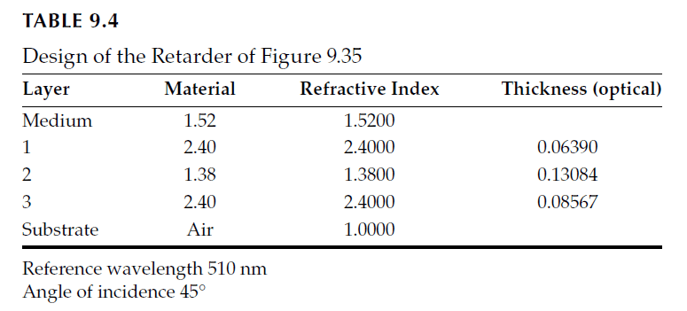
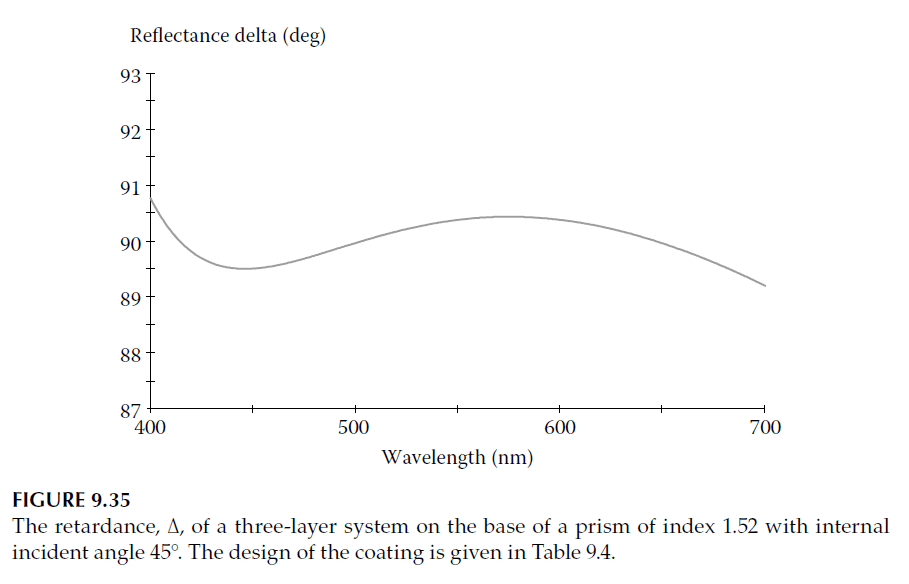
90° Retarder Design Example
A typical design for a 90° retarder operating in reflection over a broad wavelength range is shown in Table 9.4, with its performance plotted in Figure 9.35. For simplicity, the design assumes no material dispersion.
– The design achieves a variation in \(\Delta\) largely within ±0.5° across the 400–700 nm wavelength range, rising slightly at the extremes.
– To further reduce variation, additional layers can be added.
Advantages of Prism Systems
Prisms operating beyond the critical angle offer significant advantages for multilayer retarders:
– Total reflectance is ensured regardless of the dielectric layer thickness.
– High angles of propagation simplify achieving the desired retardance.
When operating below the critical angle, the performance is generally inferior, and a higher number of layers is required to achieve the same results.
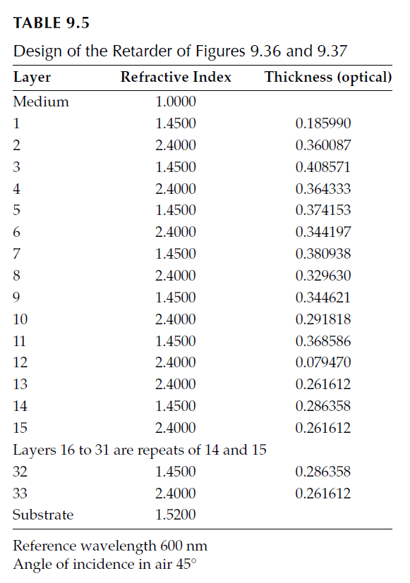
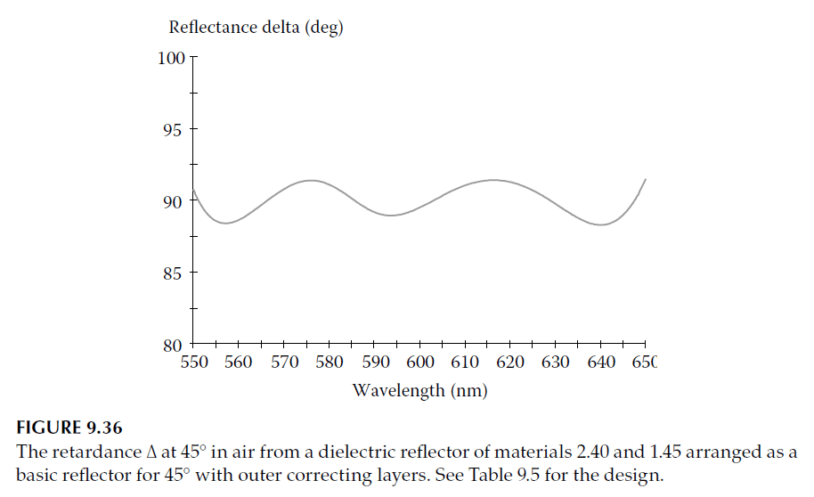
Dielectric 90° Retarder Example
An example of a 90° retarder operating at \(45^\circ\) incidence in air, using a completely dielectric approach, is provided in Table 9.5. The design includes:
1. A 21-layer quarter-wave stack designed for a reference wavelength of 600 nm and tuned to \(45^\circ\).
– Constructed from materials with indices \(n = 1.45\) and \(n = 2.40\).
2. A 12-layer overcoat ensures the desired retardance.
The target retardance specification of 90° is defined over the wavelength range 550–650 nm. However:
– The achieved variation in retardance is larger compared to internally reflected cases.
– The wavelength range for achieving the desired performance is narrower.
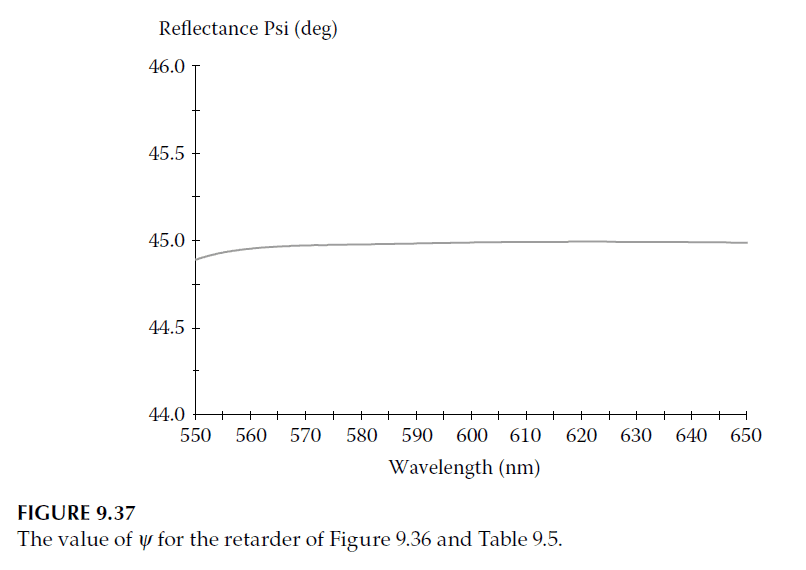
Figures 9.36 and 9.37 show the achieved retardance and the \(\psi\)-values for this design. Errors in \(\psi\) are negligible compared to those in the achieved \(\Delta\).
Practical Use in Prism Systems
Prisms are commonly used in visual optical instruments (e.g., periscopes, telescopes) to manipulate images. Internal reflection plays a key role, but introduces several challenges:
1. A single totally reflecting surface reverses the image’s parity (handedness) and makes the system sensitive to rotation.
2. Using a roof prism—two internally reflecting surfaces arranged at 90°—solves these problems by restoring parity and removing rotational sensitivity.
Polarization Issues in Roof Prisms
While the roof prism resolves parity and rotational sensitivity issues, it introduces polarization-related problems:
– Half the light meets the two surfaces in the reverse order relative to the other half.
– Each reflection affects the polarization state of the light differently, leading to doubling of the image.
When the resulting polarization perturbation consists of two components with identical orientations but a half-wave phase difference, the central maximum of the point-spread function disappears, severely degrading image quality.
To address this, the relative retardance (\(\Delta\)) at each surface of the roof must be 180°.
Achieving 180° Retardance
For a ray incident at \(45^\circ\) to the roof, with the plane of incidence bisecting the angle between the surfaces:
1. The angle of incidence on each surface is 60°.
2. The relative retardance (\(\Delta = 180^\circ\)) ensures that the p-component of polarization is flipped, effectively rotating the direction of polarization through 180°.
3. This condition holds regardless of the order in which the surfaces are encountered.
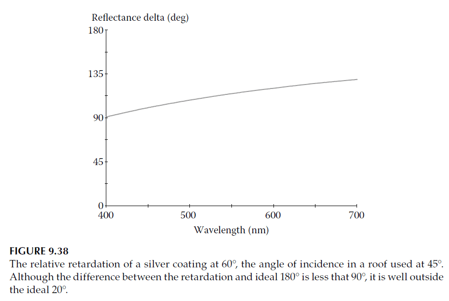
For uncoated glass surfaces (\(n = 1.52\)), the relative rotation angle at \(60^\circ\) incidence is approximately 66°, which is unsatisfactory. Simple silver coatings improve performance slightly, giving retardance values just over 90° (see Figure 9.38), but this is still insufficient for high-quality results.
Improved Designs with Thin-Film Coatings
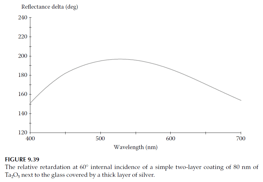
1. Simple Coatings:
A thin layer of a high-index material, such as tantalum pentoxide (approximately 80 nm thick), overcoated with silver can achieve a retardance (\(\Delta\)) close to 180°.
– This design reduces reflectance slightly, particularly at shorter wavelengths (blue end of the spectrum).
– Figure 9.39 demonstrates the performance, which lies within the ±20° tolerance suggested by Ito and Noguchi.
2. Dielectric Multilayers:
For even better performance, a multilayer dielectric coating can be used. With about five layers, accuracies within 5° can be achieved.
Conclusion
Multilayer thin-film retarders can achieve precise phase retardance over a specific wavelength range. Designs using internal reflection at angles beyond the critical angle provide the most stable and efficient performance. For roof prisms and similar applications, thin-film coatings allow the retardance (\(\Delta\)) to reach or closely approximate 180°, addressing polarization issues and ensuring high-quality optical performance. Advanced computer-aided design and synthesis further enhance the ability to meet stringent specifications efficiently.