The term rugate, derived from biology, means “corrugated.” It was initially introduced to describe structures exhibiting a regular cyclic variation in refractive index, often resembling sine or cosine waves. Such structures reflect a narrow spectral region while transmitting all others.
They behave similarly to quarter-wave stacks but do not exhibit higher-order reflection bands, making them particularly effective as notch filters for removing bright spectral lines from weaker continua. Rugate filters are especially useful in laser-related applications, including laser protection.
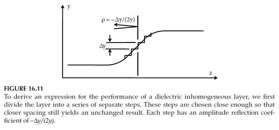
Over time, the definition has broadened to include any layer system designed to induce an inhomogeneity, whether cyclic or not. However, this section focuses primarily on the original, stricter definition of rugate filters.
Properties and Characteristics of Rugate Filters
1. Comparison with Quarter-Wave Stacks:
- A traditional quarter-wave stack consists of alternating high- and low-index layers, achieving high reflectance due to constructive interference at specific wavelengths. The high reflectance zone is limited to the wavelength for which the layers are exact quarter-waves, while the transmittance is high outside this zone.
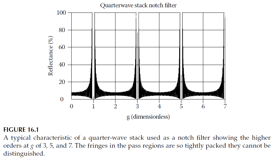
- The interference condition that creates high reflectance at a fundamental wavelength (\(\lambda_0\)) also applies to its harmonics (\(\lambda_0/3, \lambda_0/5, \lambda_0/7, \dots\)), resulting in higher-order reflectance zones that reduce the effectiveness of quarter-wave stacks as notch filters. A typical characteristic curve for a quarter-wave stack is shown in Figure 16.1.
2. Advantages of Rugate Filters:
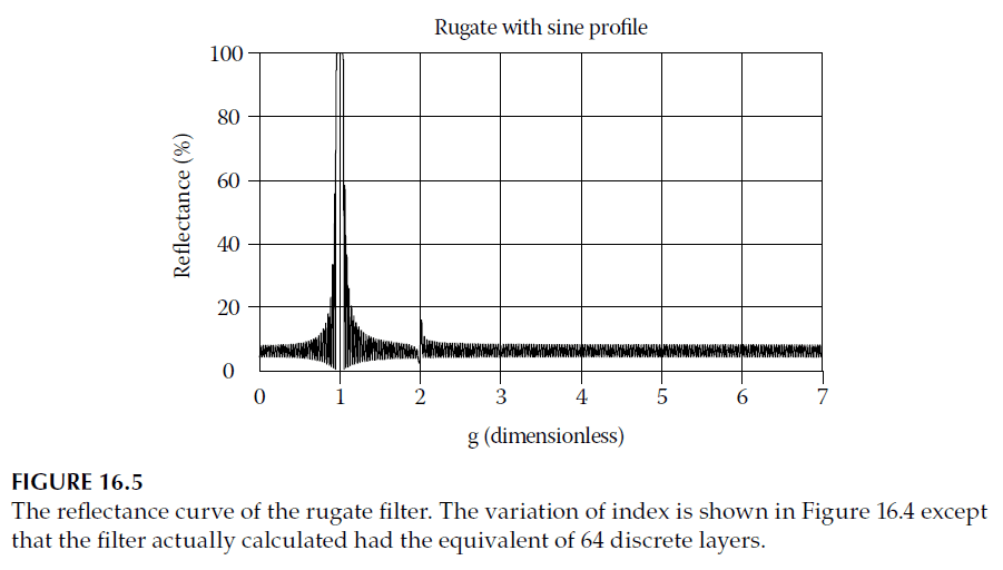
- Rugate filters eliminate higher-order reflection bands by distributing interference effects across a continuous, cyclic refractive index variation. This ensures that high reflectance occurs only at the fundamental wavelength (\(g = 1.0\)), while suppressing reflections at higher orders.
3. Role of Inhomogeneous Layers:
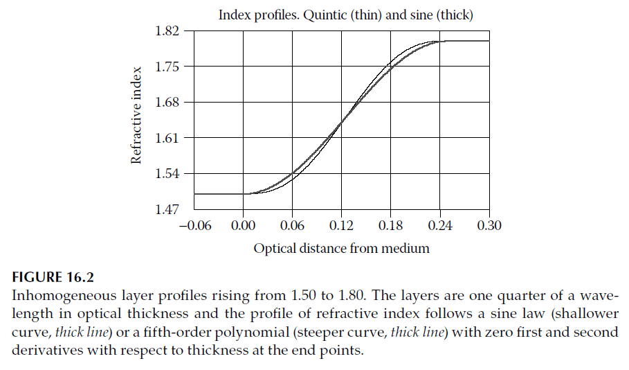
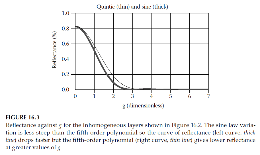
- Inhomogeneous layers serve as antireflection coatings, reducing reflectance at higher orders without affecting the fundamental peak. Figure 16.2 shows possible refractive index profiles for such layers, and their corresponding reflectance performances are depicted in Figure 16.3.
Rugate Filter Design and Challenges
1. Sinusoidal Refractive Index Profile:
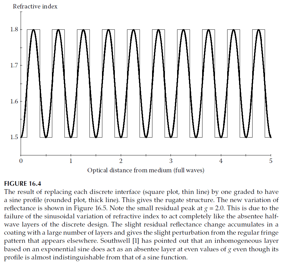
- By inserting inhomogeneous antireflection coatings at each interface in a traditional multilayer stack, the refractive index profile becomes sinusoidal, creating a rugate structure (Figure 16.4).
- These structures are robust against errors in the index profile. As long as the optical thickness at a given wavelength exceeds half a wave, reflectance remains low. Systematic errors that alter the pitch of the cycle can broaden the reflectance peak but do not significantly degrade performance unless severe.
2. Manufacturing Challenges:
- Rugate filters require smooth compositional changes to achieve the desired index profile. This necessitates active index control during deposition, unlike traditional discrete layer stacks where only optical thickness is controlled.
- Deposition techniques must manage parameters such as source temperature and deposition rate to engineer the refractive index profile accurately.
3. Discrete Layer Approximations:
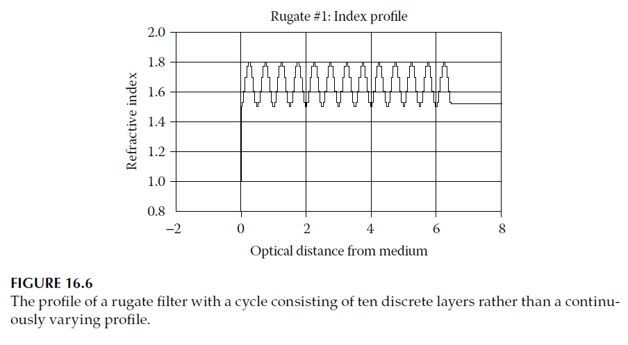
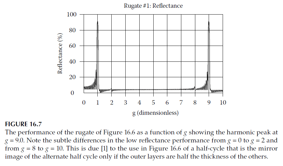
- Rugate filters can be approximated using discrete layers, creating a staircase-like index profile by dividing a single rugate period into multiple thin layers of equal optical thickness. Figure 16.6 shows a rugate profile converted into discrete layers, and its performance is shown in Figure 16.7.
Performance of Discrete Rugates
1. Behavior at Fundamental and Higher Orders:
- At \(g = 1.0\), the rugate cycle is half a wave thick, yielding high reflectance. As \(g\) increases, higher-order peaks remain suppressed until the layers become half-wave thick at a specific \(g\), where reflectance resembles that of the uncoated substrate.
- The interference patterns for increasing and decreasing \(g\) are symmetrical, resulting in predictable performance at higher harmonics. For example, a 10-layer rugate cycle suppresses higher-order peaks effectively, as illustrated in Figure 16.7.
2. Effect of Layer Cycle Complexity:
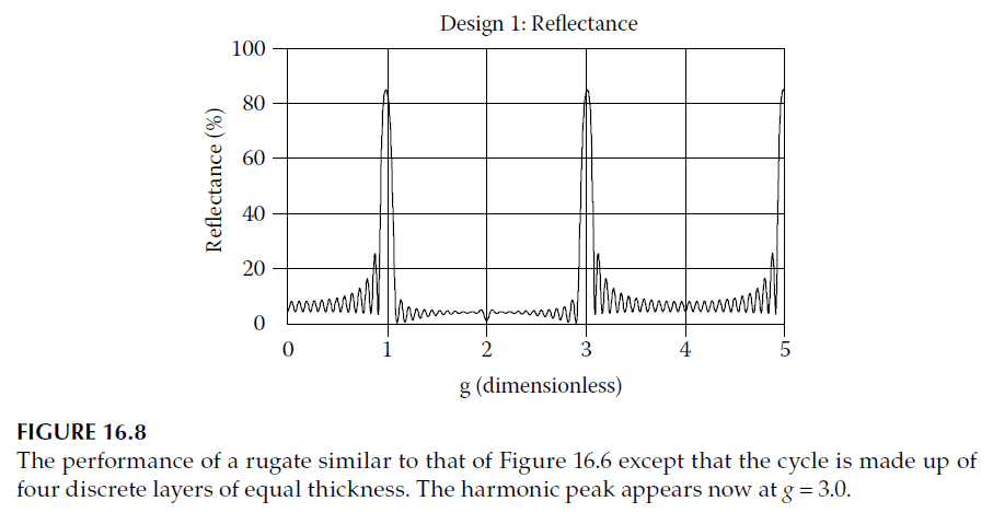
- Adding more layers to a cycle can improve suppression of higher-order peaks. For instance, a four-layer cycle suppresses the peak at \(g = 2\) better than a two-layer cycle, as shown in Figure 16.8.
Alternative Design Techniques
1. Symmetrical Layer Combinations:
- A continuous rugate profile can be approximated using symmetrical combinations of layers with fixed high and low indices. This equivalence holds for specific wavelengths and angles of incidence but deteriorates with natural dispersion and angle changes.
2. Two-Layer Approximation:
- Thin-film matrices can be approximated by pairs of layers, with the equivalent refractive index calculated using the relationship: \[d_1 = \frac{d n_2}{n_2 – n_1}, \quad d_2 = \frac{d n_1}{n_2 – n_1}\] where \(n_1\) and \(n_2\) are the indices of the two layers, \(d\) is the total thickness, and \(d_1 + d_2 = d\).
3. Example:
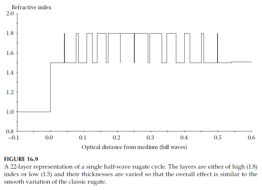
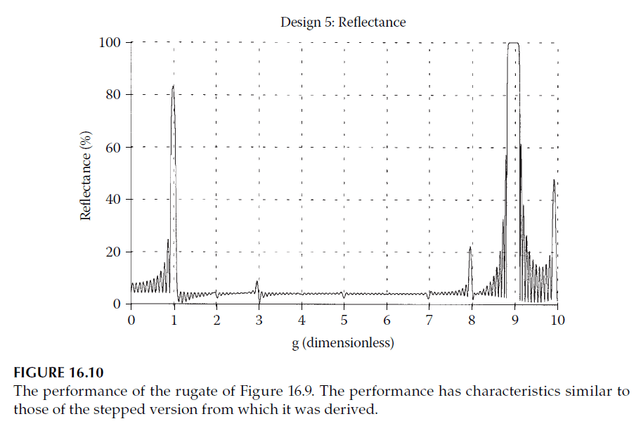
- Figure 16.9 shows a rugate cycle replaced by discrete layers using this technique, and Figure 16.10 illustrates the performance of a filter composed of 14 such cycles.
Broader Definition of Rugate Filters
The broader definition of rugate includes any continuous variation of refractive index, not necessarily cyclic. Accurate calculations for such structures involve slicing the profile into thin homogeneous sublayers and applying standard techniques.
1. Calculation Techniques:
- Thin sublayers are used to approximate the continuous profile, ensuring accurate results. Slices thinner than a quarter-wave are typically sufficient, with convergence achieved by further subdivision.
2. Vector Method:
- The vector method relates performance to the distribution of admittance through a Fourier integral: \[\Delta y = Q \cdot i \int_{-\infty}^{\infty} \exp(-i \kappa x) \, dx\] where \(Q\) represents performance, \(\kappa = 2\pi/\lambda\), and \(x\) is twice the optical thickness.
3. Design Conversion:
- Continuous profiles can be converted into discrete-layer designs, with layer thicknesses thin enough not to affect performance at the shortest wavelength of interest.
Advantages and Limitations
1. Advantages:
- Analytical connection between design and performance, enabling reverse calculation.
- Flexibility in designing filters for specific spectral properties.
2. Limitations:
- Approximation errors due to dispersion or angle changes.
- Requires expertise in selecting appropriate functions and parameters.
