In this tutorial, we assume that thin-film materials are free from absorption or other losses. To understand the qualitative performance of thin-film optical devices, several foundational principles must be recognized:
- The amplitude reflectance of light at any boundary between two media is given by \((1 – \rho) / (1 + \rho)\), where \(\rho\) represents the ratio of the optical admittances at the boundary, which is also the ratio of the refractive indices in the optical region. The reflectance (ratio of irradiances) is the square of this value.
- A phase shift occurs during reflection. When light reflects within a medium of lower refractive index compared to the adjoining medium, the phase shift is \(180^\circ\). Conversely, if the reflection occurs within a medium of higher refractive index, there is no phase shift.
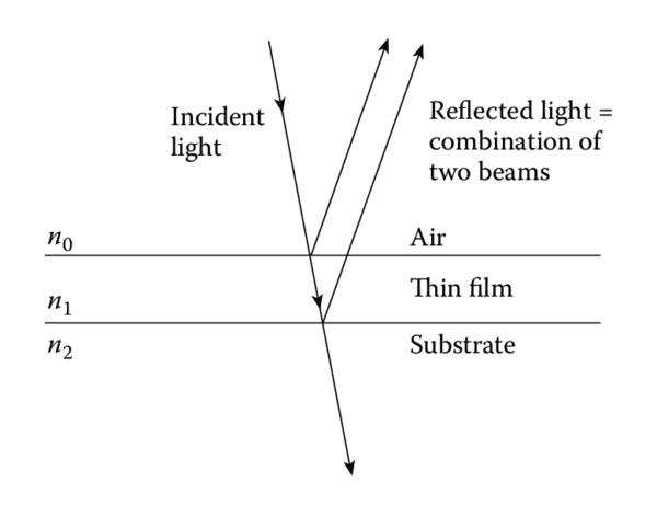
- When light is split into two components by reflection at the top and bottom surfaces of a thin film, the beams recombine. If their relative phase shift is \(180^\circ\), the amplitudes subtract (destructive interference). If the relative phase shift is \(0^\circ\) or a multiple of \(360^\circ\), the amplitudes add (constructive interference). Intermediate phase shifts result in partial interference.
Antireflection Coatings
Antireflection coatings rely on the cancellation of light reflected from the upper and lower surfaces of a thin film (Figure 1.1). Let the refractive indices of the substrate, film, and incident medium (usually air) be \(n_{\text{sub}}\), \(n_1\), and \(n_0\), respectively. For full cancellation of reflected beams, the amplitude of light reflected at each boundary must be equal, which implies that \(n_1 = \sqrt{n_0 n_{\text{sub}}}\).

The refractive index of the thin film should, therefore, lie between those of air \((n_0 \approx 1)\) and the substrate \((n_{\text{sub}} \geq 1.52)\). To achieve a \(180^\circ\) relative phase shift for beam cancellation, the optical thickness of the film must be one-quarter wavelength. A simple antireflection coating consists of a single thin film with a refractive index equal to the square root of the substrate’s index and a quarter-wavelength optical thickness. Advanced coatings with multiple layers provide broader wavelength coverage and are discussed in later tutorials.
High-Reflectance Coatings and Filters
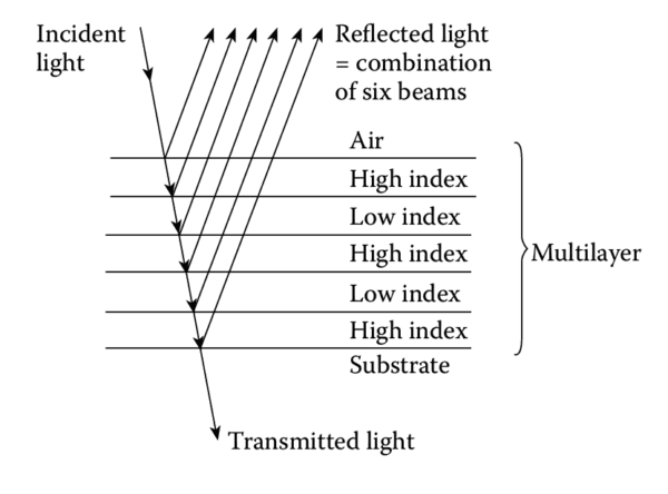
Another essential thin-film structure is a stack of alternating high- and low-refractive-index layers, each one-quarter wavelength thick (Figure 1.2). In these stacks:
- Light reflecting within high-index layers experiences no phase shift.
- Light reflecting within low-index layers undergoes a \(180^\circ\) phase shift.
This configuration ensures that reflected components from successive boundaries recombine constructively at the surface, producing high reflectance. By increasing the number of layers, the effective reflectance can be made extremely high. However, the reflectance remains high only within a limited wavelength range, determined by the refractive index ratio of the layers. Outside this range, reflectance drops abruptly, making the quarter-wave stack a foundational building block for thin-film filters.

Applications of quarter-wave stacks include:
- Longwave-pass and shortwave-pass filters.
- Bandstop filters.
- Laser mirrors.
- Reflectors in thin-film Fabry-Perot interferometers (Figure 1.3).
The Fabry-Perot interferometer includes a spacer layer, typically half a wavelength thick, sandwiched between two high-reflectance coatings. This structure produces extremely high transmission over a narrow wavelength band, centered on the wavelength for which the spacer thickness equals a multiple of half a wavelength. Coupling multiple Fabry-Perot filters in series can create filters with more rectangular passbands.

Real-World Considerations
In practical applications, thin-film materials are usually assumed to have negligible absorption or loss, making filters nearly transparent. Reflection and transmission properties are complementary, a feature exploited in devices like dichroic beam splitters for color separation in projection systems.
Accurate performance evaluations must consider multiple reflections within the layers. These calculations involve solving Maxwell’s equations in stratified media, which are addressed in a later tutorial. The matrix method, representing each film with a \(2 \times 2\) matrix, simplifies these solutions. Although the matrices themselves are simple, manually calculating the properties of multilayer systems—especially those with absorption or broad spectral regions—is tedious. Computers and programmable calculators make these calculations more efficient, though skill and experience remain critical for successful design.
Thin-Film Design Techniques
Designing a multilayer thin-film system involves finding an arrangement of layers to meet specific performance requirements. This process is more complex than simply calculating the properties of an existing design. A typical approach combines:
- Analytical techniques.
- Experience and intuition.
- Predefined building blocks.
After an initial design is proposed, a computer calculates its performance. Adjustments are made iteratively until a satisfactory solution is found. This process, called refinement, optimizes parameters to minimize discrepancies between the achieved and desired performance. A related concept, synthesis, constructs designs from scratch based solely on performance specifications.
Refinement works best when starting with a design close to the target performance, while synthesis requires carefully structured search procedures due to the virtually infinite possibilities. Modern advancements in computing have enhanced automatic design synthesis, but skilled practitioners still outperform purely automated systems in most cases.
Manufacturing and Practical Limitations
The primary limitation in thin-film filter performance lies not in design techniques but in manufacturing precision. Producing layers with accurate optical constants and thicknesses is critical.
Common manufacturing methods, classified as physical vapor deposition, involve condensing solid films from the vapor phase. Thermal evaporation, a traditional technique, remains widely used but has been supplemented by energetic processes. These newer methods improve film solidity by introducing mechanical momentum to the growing layer, either through deliberate bombardment or higher energy deposition of material.
