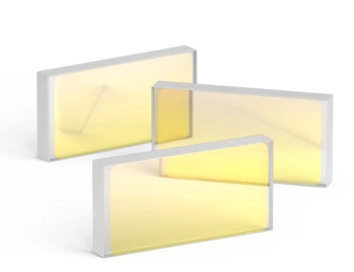
What are thin film polarizers?
Thin film polarizers are optical devices designed to selectively transmit light waves of a specific polarization while reflecting or absorbing other polarization states. They are commonly used in various applications, including photography, display technology, and optical instrumentation.
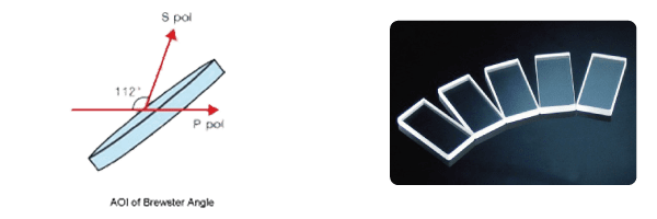
They separate s- and p-polarized components at a specific wavelength. Due to their high damage threshold, thin film polarizers are used in place of Glan laser polarizing prisms or cube polarizing beamsplitters in high-energy laser applications.
Key Features:
Construction: Thin film polarizers are typically made by layering multiple thin films of materials with different refractive indices. This structure exploits the principle of constructive and destructive interference to enhance the transmission of certain polarizations.
Polarization Mechanism: The thin films create a condition where light waves of one polarization (usually transverse electric, or TE) are transmitted, while waves of the orthogonal polarization (transverse magnetic, or TM) are reflected or absorbed.
Applications:
- Photography: To reduce reflections and enhance contrast in images.
- Displays: In LCDs and other displays to control light and improve image quality.
- Scientific Instruments: For precise measurement and analysis in optics and photonics.
Performance Characteristics: Thin film polarizers can have high polarization efficiency, a broad spectral range, and compact size, making them versatile in various optical setups.
Overall, their ability to manipulate light makes thin film polarizers essential in many modern optical applications.
Technical Details of Thin Film Polarizers
- Design Structure:
- Composed of multiple layers of dielectric materials with varying refractive indices.
- Designed for specific wavelengths (e.g., visible light, infrared).
- Polarization Efficiency:
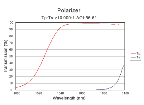
- High extinction ratios (often >1000:1), indicating effective suppression of unwanted polarization.
- Transmission rates for the preferred polarization (often around 90% or higher).
- Spectral Range:
- Usual ranges include UV, visible, and IR, tailored for specific applications.
- May provide graphs or charts showing transmission and reflection characteristics across wavelengths.
- Optical Quality:
- Low optical losses to ensure minimal loss of intensity.
- High damage thresholds, important for laser applications.
- Physical Dimensions:
- Available in various sizes and thicknesses, customizable based on application needs.
- May specify substrate material (e.g., glass, quartz) for compatibility with different setups.
- Applications:
- Photographic filters, LCD screens, laser systems, and scientific instrumentation.
- Mounting Options:
- Options for integration into optical systems, including adhesives or mechanical mounts.

Specifications
| Material | BK7 or Fused Silica |
| Dimensions | 4mm ~ 80mm, round or square |
| Surface Quality | 10/5 |
| Surface Flatness | λ/[email protected] |
| Parallelism | 30″ |
| Extinction Ratio (Tp/Ts) | 200:1 ~ 10,000:1 |
| Angle of Incidence (AOI) | 56.5° or 45° (Or Custom Design) |
| Damage Threshold | 10J/cm^2, 10ns pulse@1064nm |
| Typical Wavelength | 1064nm, 532nm (Or Custom Design) |
| Transmitted Wavefront Error | λ/[email protected] |

