As explored in previous tutorials, the characteristics of coatings change when tilted with respect to the incident illumination, and these changes depend significantly on the angle of incidence. We have examined the shifts induced in narrowband filters, a relatively straightforward case. In such scenarios, the tilt angle is typically small, and the primary impact is on the phase thickness of the layers. This effect is generally uniform for each plane of polarization.
For larger tilt angles, however, the situation becomes more complex. The admittances of the layers are also affected, resulting in different performance characteristics for each plane of polarization. Some applications exploit these differences to construct devices like phase retarders and polarizers. Conversely, these differences can also present challenges, particularly when polarization-dependent performance is undesirable. Although the effects cannot be entirely eliminated, they can often be mitigated to achieve more acceptable results.
An intriguing phenomenon occurs with dielectric-coated reflectors. Under specific conditions and at reasonably high angles of incidence, sharp absorption bands can form for one plane of polarization. This can cause issues with dielectric-overcoated reflectors, such as protected silver coatings.
This tutorial begins by extending the admittance diagram to include tilting effects, providing a qualitative explanation of the behavior of various tilted coatings, including overcoated reflectors. This involves a slight modification of the conventional tilted admittance framework. The tutorial then covers:
- Polarizers: An overview of designs and performance characteristics.
- Phase Retarders: An explanation of how they utilize polarization differences.
- Mitigation of Polarization Splitting: A discussion on coatings like dichroic filters, where polarization splitting is undesirable, along with techniques to reduce this effect.
- Antireflection Coatings at High Angles of Incidence: A description of their design and performance.
Some of the material in this tutorial overlaps with earlier discussions. However, presenting it here within a consistent and unified framework offers a clearer understanding of the topic. As such, some repetition of previously covered material has been included to reinforce key concepts and align them with the context of tilted coatings.
Modified Admittances and the Tilted Admittance Diagram
The admittances and phase thickness of a film illuminated at oblique incidence were introduced in previous tutorials and used to study the performance of coatings, including narrowband filters. For dielectric materials, these are given by:
\[
\delta = \frac{2\pi nd \cos\vartheta}{\lambda}
\tag{9.1}
\]
\[
\eta_s = Y \cos\vartheta
\tag{9.2}
\]
\[
\eta_p = \frac{Y}{\cos\vartheta}
\tag{9.3}
\]
where:
\[
n_0 \sin\vartheta_0 = n_1 \sin\vartheta_1 = n_2 \sin\vartheta_2 = \dots
\tag{9.4}
\]
Here, \(n, Y, d,\) and \(\vartheta\) represent the refractive index, admittance, physical thickness, and angle of incidence, respectively, for a particular material. The subscript \(0\) denotes the incident medium.
Adjustments for Complex Refractive Indices
When the refractive index (\(n\)) and admittance (\(Y\)) are complex, we adopt a modified approach. The incident medium is assumed to have no absorption, allowing the angle of incidence (\(\vartheta\)) to become complex to support a complex \(\sin\vartheta\). To simplify calculations, we focus on \(\cos\vartheta\), where:
\[
\cos^2\vartheta = 1 – \sin^2\vartheta
\]
For absorbing materials, this leads to:
\[
\delta = \frac{2\pi}{\lambda} d \sqrt{n_0^2 – k^2 – n_0^2 \sin^2\vartheta_0 – i 2 n_0 k}
\tag{9.5}
\]
The square root must be taken in the fourth quadrant. The admittances are given by:
\[
\eta_s = \sqrt{n^2 – k^2 – n_0^2 \sin^2\vartheta_0 – i 2 n k}
\tag{9.6}
\]
\[
\eta_p = \frac{\eta_s}{n – ik}
\tag{9.7}
\]
These expressions reduce to Equations (9.1)–(9.3) when \(\cos\vartheta\) is real.
Multilayer Properties at Oblique Incidence
The multilayer properties for non-normal incidence involve using the above expressions instead of those for normal incidence. The tilted admittance values are applied to both the films and the incident medium.
The admittance diagram becomes more complex because the admittance of the incident medium changes with polarization and the angle of incidence. Each combination of angle and polarization requires unique isoreflectance and isophase contours. To address this, Thelen introduced a method of scaling the admittances.
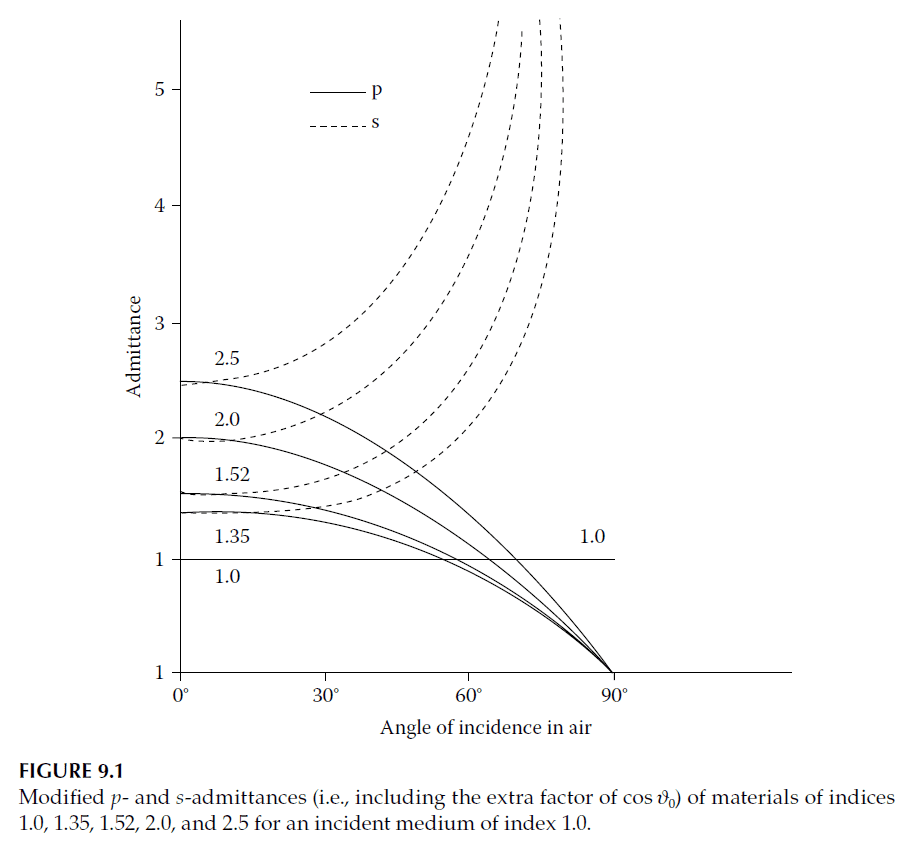
Modified Admittances
By dividing the s-polarized admittance and multiplying the p-polarized admittance by \(\cos\vartheta_0\), the admittance of the incident medium at normal incidence is preserved for both polarizations. These modified admittances are defined as:
For dielectric materials:
\[
\eta_s = \frac{Y \cos\vartheta}{\cos\vartheta_0}
\tag{9.8}
\]
\[
\eta_p = \frac{Y \cos\vartheta_0}{\cos\vartheta}
\tag{9.9}
\]
For absorbing materials:
\[
\eta_s = \frac{\sqrt{n^2 – k^2 – n_0^2 \sin^2\vartheta_0 – i 2 n k}}{\cos\vartheta_0}
\tag{9.10}
\]
\[
\eta_p = \frac{\eta_s}{n – ik}
\tag{9.11}
\]
These modified admittances ensure that the isoreflectance and isophase contours of the admittance diagram remain unchanged at non-normal incidence.
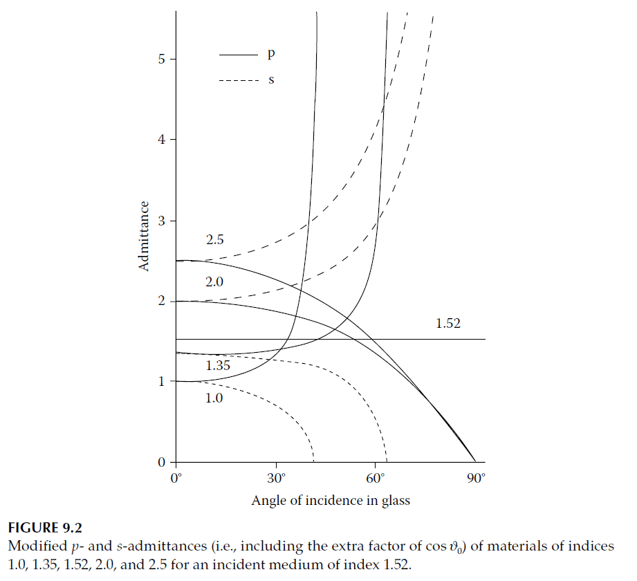
Critical and Brewster Angles
For angles less than the critical angle (\(\vartheta_c\)), the admittances are real. The Brewster angle (\(\vartheta_B\)) occurs where the p-polarized single-surface reflectance is zero, corresponding to the crossing point of p-admittance curves with \(n = 1\). At angles beyond \(\vartheta_c\), admittances become imaginary.
Behavior of Antireflection Coatings
For antireflection coatings at high angles of incidence, the required admittance for a perfect single-layer coating often lies outside the range of practical materials for s-polarization. For p-polarization, however, suitable solutions exist in the range of 50°–70°. At the Brewster angle, no coating is needed for p-polarization.
MacNeille Polarizing Beam Splitter
In materials with indices both higher and lower than the incident medium, the intersection of p-admittance curves corresponds to a behavior similar to a thick slab of material. This principle underlies the MacNeille polarizing beam splitter.
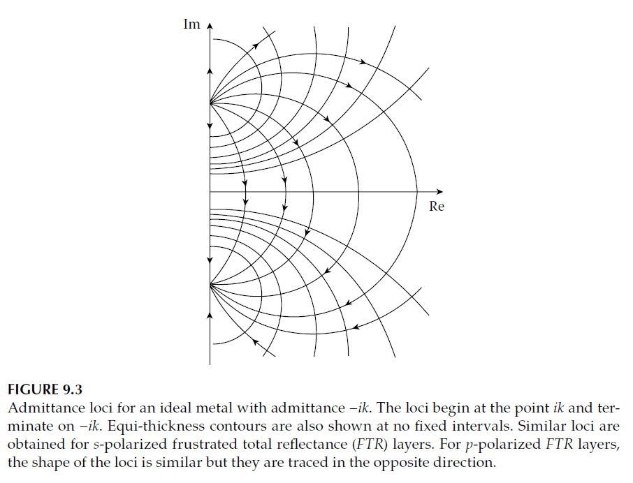
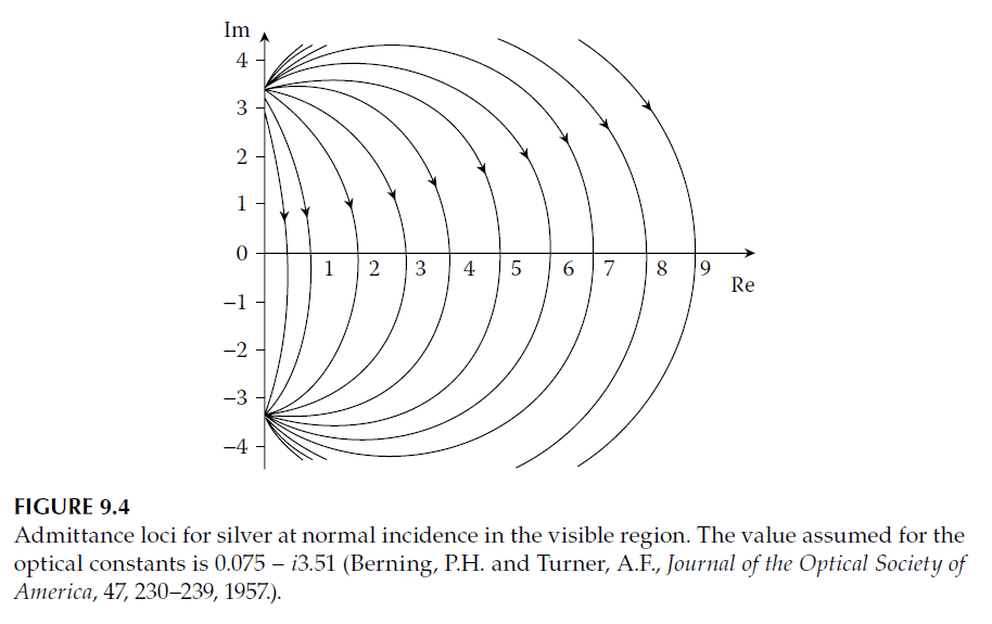
Metallic Layers at Oblique Incidence
The loci of metallic layer admittances differ from dielectric layers. For high-performance metals, the loci are approximately circular and centered near the real axis. At oblique incidence:
\[
\delta = \frac{2\pi}{\lambda} (n – ik)d
\tag{9.12}
\]
changes to:
\[
\delta = \frac{2\pi}{\lambda} d \sqrt{n_0^2 – k^2 – n_0^2 \sin^2\vartheta_0 – i 2 n_0 k}
\tag{9.13}
\]
At high angles, the real part of the phase thickness slightly decreases, while the imaginary part increases. For high-performance metals, the loci expand for s-polarization and contract for p-polarization, retaining their general form.
Conclusion
The modified admittance approach simplifies the analysis of tilted coatings, retaining normal incidence admittance values for ease of use. This framework supports the design of high-performance coatings, polarizers, and beam splitters, addressing the challenges of oblique incidence in both dielectric and metallic systems.