Equivalent Layers
The use of quarter-wave or multiple quarter-wave layers is advantageous during the initial stages of antireflection coating design because these layers produce symmetrical characteristic curves around \( g = 1.0 \). However, challenges arise during construction since the specified indices often do not match readily available materials. Although mixing materials of higher and lower indices to create intermediate index layers has been effective, a more straightforward approach involves replacing the layers with equivalent combinations of just two materials: one with a high index and one with a low index.
To illustrate, consider two materials with indices of 2.30 (e.g., titanium dioxide) and 1.38 (e.g., magnesium fluoride).
Vermeulen’s Technique
Vermeulen’s method replaces a quarter-wave layer with a two-layer equivalent. This approach is based on the analysis used for two-layer antireflection coatings. It assumes a starting and terminating locus point on the real axis for a specific wavelength. While effective under ideal conditions, this method becomes less accurate as conditions deviate from these ideals.
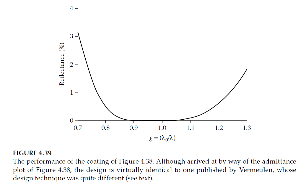
For instance, consider starting with an admittance of 1.52 and terminating at 1.9044 to ensure that the outermost 1.38-index quarter-wave layer terminates at 1.00 on the real axis. Using Equations (4.6), the high- and low-index layers’ thicknesses are calculated as:
- High-index layer: \( 0.05217 \) full waves
- Low-index layer: \( 0.07339 \) full waves.
This design, combined with a half-wave layer of index 2.30 and a quarter-wave layer of index 1.38, produces the characteristic curve shown in Figure 4.39.

Epstein’s Technique
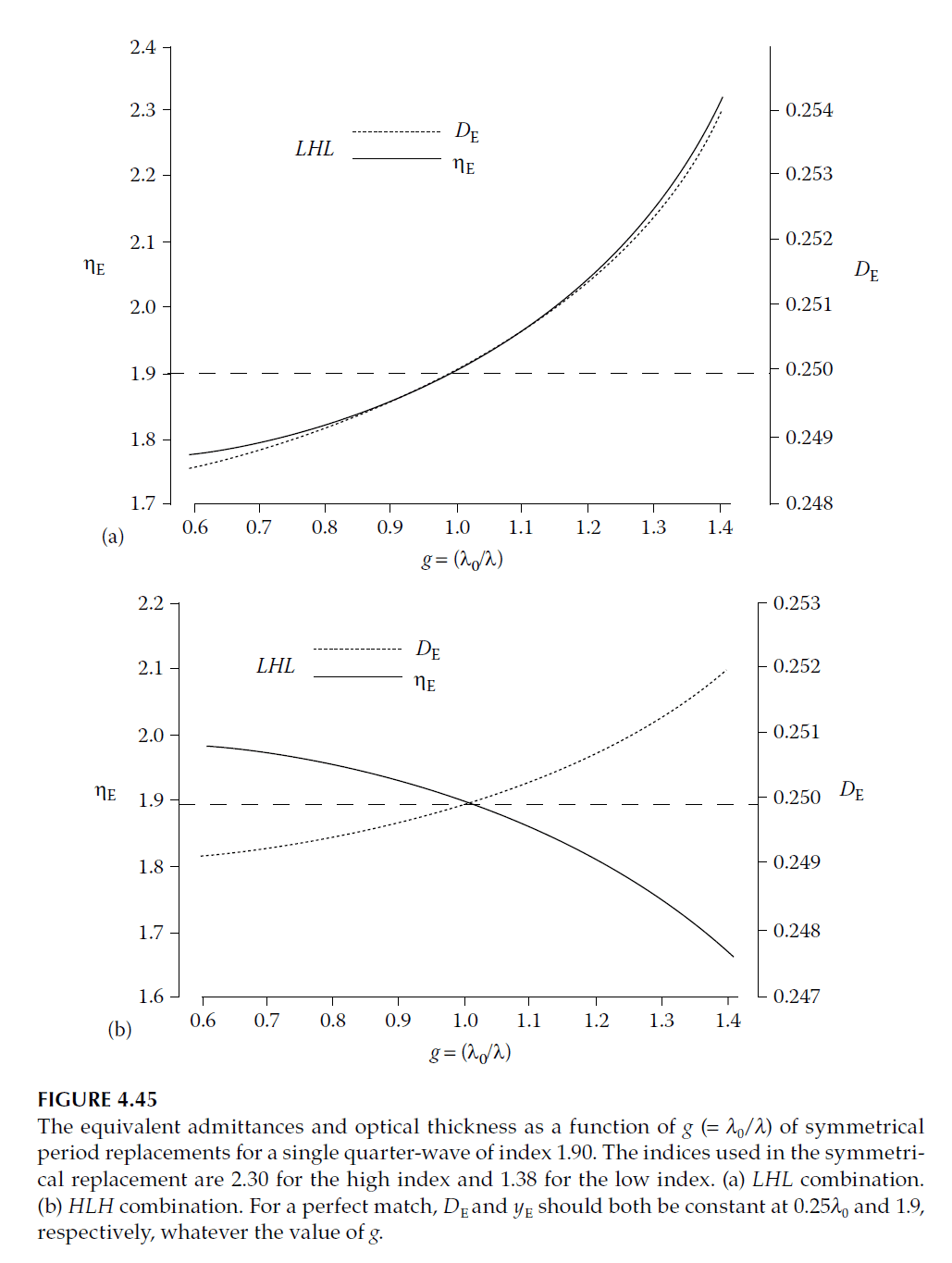
Epstein’s approach utilizes symmetrical periods and Herpin admittance. Symmetrical combinations (e.g., \( ABA \)) act as single layers with equivalent phase thickness (\( \gamma \)) and equivalent optical admittance (\( y_E \)).
Equivalent Thickness and Admittance
For a symmetrical period \( ABA \):
\[
y_E = \frac{y_A}{y_B \sin^2 \delta_A + y_A \cos^2 \delta_A + y_B \cos^2 \delta_B – y_A \cos \delta_A \cos \delta_B}
\]
\[
\cos \gamma = \cos \delta_A \cos \delta_B – \frac{y_B \sin \delta_A \sin \delta_B}{y_A}
\]
To replace a quarter-wave layer, set \( \gamma = \pi/2 \), giving:
\[
\cos^2 \delta_A = \frac{y_B^2 + y_A y_E}{y_B^2 + y_E y_A}
\]
Substituting the values of \( y_E \) and \( \delta_B \) leads to expressions for the optical thicknesses \( n_A d_A \) and \( n_B d_B \).
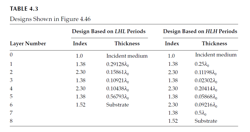
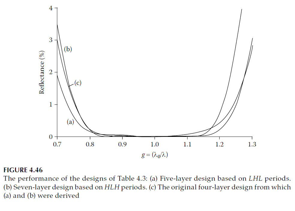
Example: Four-Layer Coating Replacement
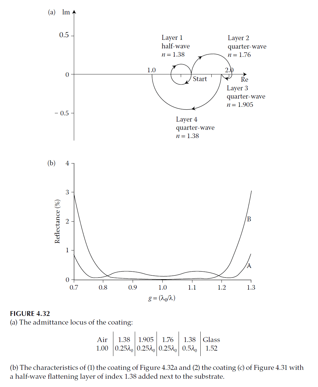
Consider the four-layer coating in Figure 4.32. The layers with indices 2.13 and 1.90 can be replaced using either \( HLH \) or \( LHL \) combinations:
- For 2.13 index:
\[
\text{HLH: } 2.30 (0.04128) – 1.38 (0.15861) – 2.30 (0.04128)
\]
\[
\text{LHL: } 1.38 (0.11193) – 2.30 (0.09216) – 1.38 (0.11193)
\] - For 1.90 index:
\[
\text{HLH: } 2.30 (0.06793) – 1.38 (0.1438) – 2.30 (0.06793)
\]
\[
\text{LHL: } 1.38 (0.09216) – 2.30 (0.09216) – 1.38 (0.09216)
\]
The spectral performance of these coatings, shown in Figure 4.46, is slightly inferior to the original due to effective dispersion.
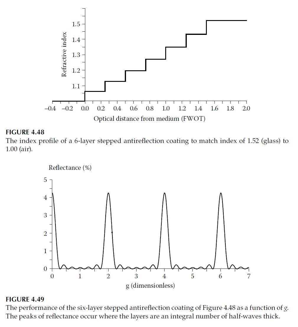
Schulz’s Index Distribution
Schulz proposed a smooth index gradient design to optimize antireflection coatings. This involves calculating layer indices using:
\[
y_f = \sqrt[q+1]{y_{\text{sub}} y_0}
\]
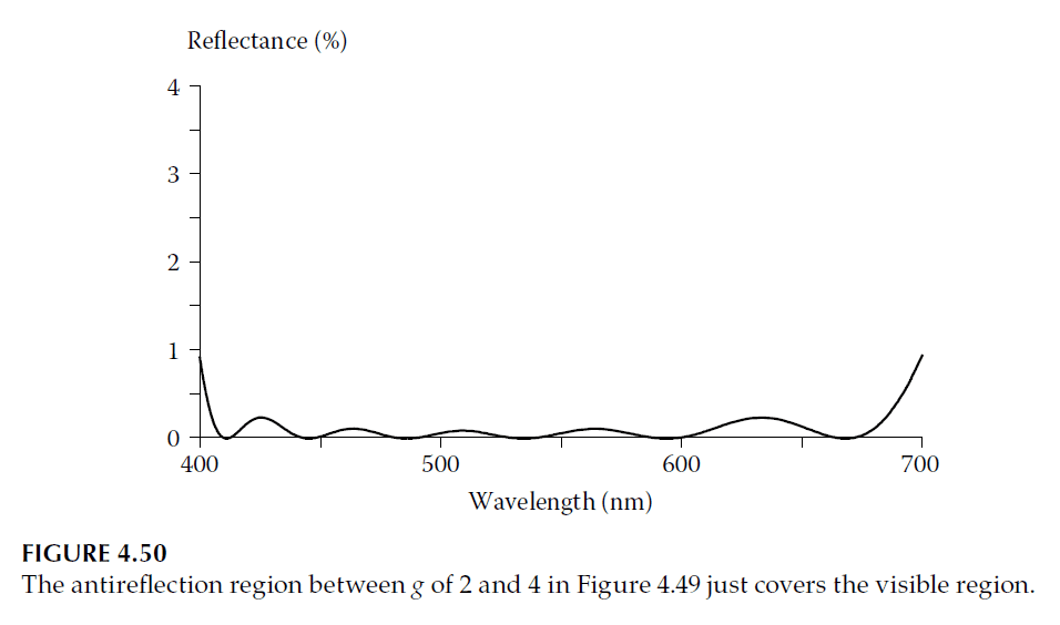
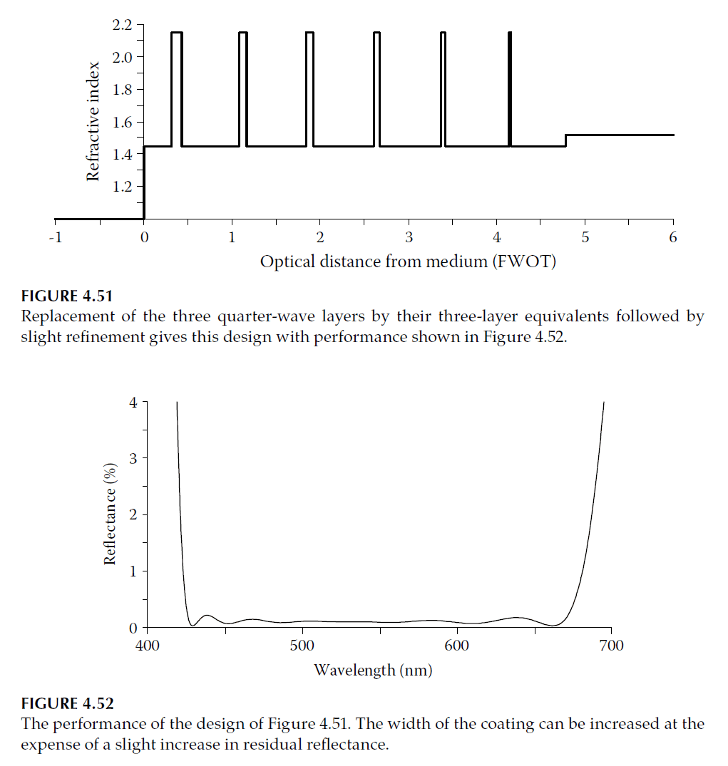
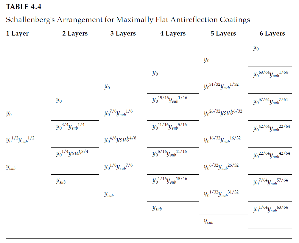
Performance of a six-layer coating based on this distribution is shown in Figures 4.49 and 4.50. Refining the design by replacing low-index quarter-waves with three-layer symmetrical combinations yields Figure 4.51 and Figure 4.52.
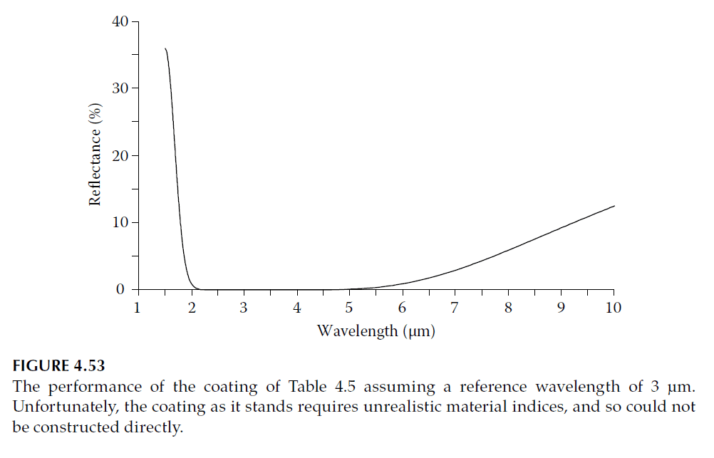
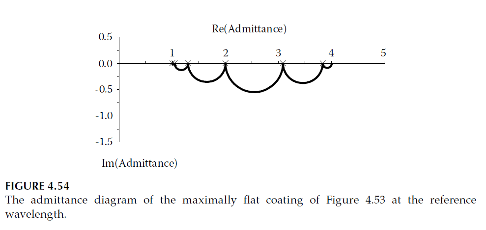
Schallenberg’s Maximally Flat Design
Schallenberg demonstrated that a maximally flat design minimizes ripple in the antireflected region. For coatings with quarter-wave layers, admittances follow a geometric progression:
\[
y_{i+1} = \sqrt{y_i \cdot y_{\text{sub}}}
\]
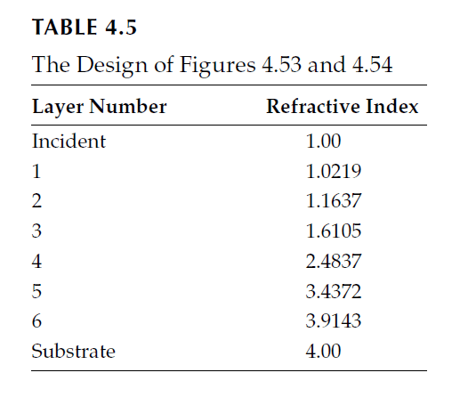
Performance of a six-layer coating for germanium (index 4.00) is illustrated in Figures 4.53 and 4.54.