Overview of Laser Induced Damage Threshold (LIDT) Measurement and Application
Understanding the Laser Induced Damage Threshold (LIDT) is essential when selecting optics for specific laser applications, as the LIDT varies depending on the type of laser used. For continuous wave (CW) lasers, damage typically results from thermal effects due to absorption in the coating or substrate. In contrast, pulsed lasers often cause damage by first stripping electrons from the optic’s lattice structure before thermal effects occur.
This guideline assumes optics are at room temperature and in pristine condition (free of scratches, contamination, etc.), as any dust or particles on the surface can lower the LIDT and lead to damage more readily. Keeping optics clean is crucial to maintain their integrity under laser exposure. For more information on cleaning optics, please see our Optics Cleaning tutorial.
Testing Method
Notch Optics performs Laser Induced Damage Threshold (LIDT) testing in accordance with ISO/DIS 11254 and ISO 21254 standards.
The testing process begins with directing a low-power/energy laser beam at the optic under evaluation. The optic is exposed at 10 different locations for 30 seconds in continuous wave (CW) mode or for a specified number of pulses in pulsed mode (pulse repetition frequency provided). After each exposure, a microscope (~100X magnification) is used to inspect for any visible damage on the optic.
The number of damaged locations at each power/energy level is recorded. The power/energy level is then adjusted, and the optic is exposed at 10 new locations. This process continues until damage is observed. The damage threshold is determined as the highest power/energy the optic can tolerate without sustaining damage.
A histogram, similar to the one below, illustrates the testing results of a sample mirror.
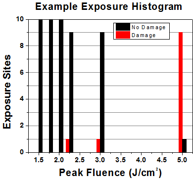
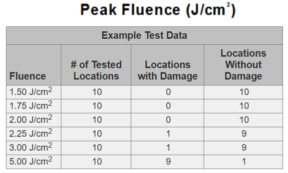
According to the test, the damage threshold of the mirror was 2.00 J/cm² (532 nm, 10 ns pulse, 10 Hz, Ø0.803 mm). It’s important to note that these tests are conducted on clean optics, as dirt and contamination can greatly reduce a component’s damage threshold. While these results represent a single coating run, Notch Optics provides damage threshold specifications that account for potential coating variances.
Continuous Wave (CW) and Long-Pulse Lasers
Optical damage from continuous wave (CW) lasers typically results from surface melting caused by absorbed laser energy or from damage to the optical coating (e.g., antireflection coatings). Pulsed lasers with pulse durations exceeding 1 µs are generally treated as CW lasers in Laser Induced Damage Threshold (LIDT) evaluations.
For pulse lengths between 1 ns and 1 µs, damage may occur due to either absorption or dielectric breakdown, making it necessary to check both CW and pulsed LIDT values. Absorption may arise from intrinsic properties of the optic or from surface irregularities, so LIDT values are valid only for optics meeting or exceeding the manufacturer’s surface quality specifications.
While many optics tolerate high-power CW lasers, certain types—like cemented optics (e.g., achromatic doublets) and highly absorptive optics (e.g., ND filters)—have lower CW damage thresholds due to absorption or scattering within the cement or metal coating. Pulsed lasers with high pulse repetition frequencies (PRF) may also exhibit CW-like behavior, though the potential for damage is influenced by factors like absorption and thermal diffusivity.
For high PRF lasers, both average and peak powers should be compared to CW power thresholds, particularly as highly transparent materials show little to no reduction in LIDT with increasing PRF.
To apply an optic’s specified CW damage threshold effectively, the following parameters are necessary:
- Laser Wavelength
- Beam Diameter (1/e²)
- Approximate Beam Intensity Profile (e.g., Gaussian)
- Linear Power Density (total power divided by 1/e² beam diameter)
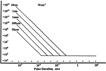
Notch Optics expresses LIDT for CW lasers in terms of linear power density (W/cm). This linear power density LIDT can apply across any beam diameter without requiring adjustments for spot size changes, as illustrated in the adjacent graph. Average linear power density can be calculated using the following formula.
\[\text{Linear Power Density}=\frac{\text{Power}}{\text{Beam Diameter}}\]
The calculation above assumes a uniform beam intensity profile. If the beam has hotspots or a non-uniform intensity profile, you’ll need to approximate the maximum power density. For example, a Gaussian beam typically has a peak power density about twice that of a uniform beam (see illustration).
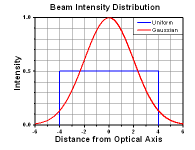
Next, compare the calculated maximum power density to the specified Laser Induced Damage Threshold (LIDT) of the optic. If the optic was tested at a different wavelength than your operating wavelength, scale the damage threshold accordingly.
A practical rule is that the damage threshold varies linearly with wavelength, meaning it decreases at shorter wavelengths. For instance, an LIDT of 10 W/cm at 1310 nm would scale down to 5 W/cm at 655 nm.
\[\text{Adjusted LIDT}=\text{LIDT Power}\left(\frac{\text{Your Wavelength}}{\text{LIDT Wavelength}}\right)\]
While this rule of thumb provides a general trend, it is not a precise analysis of LIDT as it relates to wavelength. In continuous wave (CW) applications, for example, damage is more heavily influenced by absorption in the coating and substrate, which does not always scale predictably with wavelength. This guideline provides a useful starting point for estimating LIDT, but if your operating wavelength differs from the specified LIDT wavelength, please contact Notch Optics Technical Support for assistance. If your calculated power density is below the adjusted LIDT, the optic should be suitable for your application.
Please note that we include a buffer between the published damage thresholds and our test results to account for batch-to-batch variations. Upon request, we can provide individual test results and a testing certificate for a similar optic (without damaging the customer’s optic). Please be aware that testing may incur additional costs or lead times. Contact Technical Support for further details.
Pulsed Lasers
Pulsed lasers often damage optics through mechanisms distinct from those of continuous wave (CW) lasers. Instead of heating the optic to cause damage, pulsed lasers generate intense electric fields that can induce dielectric breakdown in the material. Comparing an optic’s Laser Induced Damage Threshold (LIDT) specification to your pulsed laser can be challenging, as different pulse lengths create distinct damage regimes. The highlighted columns in the table below show the pulse lengths relevant to our specified LIDT values.
For pulse durations shorter than 10⁻⁹ seconds, reliable comparison to our LIDT values is difficult. In this ultra-short-pulse regime, mechanisms like multiphoton-avalanche ionization dominate as the primary damage process. Pulses ranging between 10⁻⁷ and 10⁻⁴ seconds can cause damage either by dielectric breakdown or thermal effects, so it’s essential to evaluate both CW and pulsed damage thresholds when determining an optic’s suitability for your application.

When comparing an LIDT specified for a pulsed laser to your laser’s parameters, you’ll need the following information:
- Wavelength of Your Laser
- Energy Density of Your Beam: Calculate as the total energy divided by the 1/e² area (J/cm²).
- Pulse Length of Your Laser
- Pulse Repetition Frequency (PRF)
- Beam Diameter (1/e²)
- Approximate Beam Intensity Profile (e.g., Gaussian)
For short pulses, expressing LIDT as energy density provides a consistent metric regardless of beam diameter, as shown in the accompanying graph.
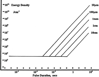
In this regime, the LIDT expressed in energy density applies uniformly across different beam diameters without needing to adjust for spot size variations. This calculation presumes a uniform intensity profile, but you must adjust for hotspots or other nonuniform profiles to estimate a maximum energy density. For instance, a Gaussian beam typically has a peak energy density twice that of the 1/e² beam area.
Now, compare the calculated maximum energy density to the specified LIDT for the optic. If the optic was tested at a different wavelength than your operating wavelength, adjust the damage threshold accordingly.
A practical rule of thumb is that the damage threshold follows an inverse square root relationship with wavelength; thus, as the wavelength shortens, the damage threshold decreases. For example, a LIDT of 1 J/cm² at 1064 nm scales down to 0.7 J/cm² at 532 nm.
\[\text{Adjusted LIDT}=\text{LIDT Energy}\displaystyle\sqrt{\frac{\text{Your Wavelength}}{\text{LIDT Wavelength}}}\]
With the wavelength-adjusted energy density calculated, you can proceed to the next steps.
Consider Beam Diameter: Beam diameter is crucial when comparing damage thresholds. While LIDT values (expressed in J/cm²) are theoretically independent of spot size, larger beam sizes are more likely to expose a greater number of surface defects, which can increase LIDT variance. For the data provided here, a beam diameter of less than 1 mm was used to measure LIDT. For beam sizes exceeding 5 mm, the LIDT (J/cm²) may no longer scale independently of beam diameter due to the likelihood of encountering more defects.
Adjust for Pulse Length: Pulse duration also impacts the amount of energy an optic can tolerate. For pulse widths between 1 and 100 ns, an approximation for compensating the pulse length is as follows:
\[\text{Adjusted LIDT}=\text{LIDT Energy}\displaystyle\sqrt{\frac{\text{Your Pulse Length}}{\text{LIDT Pulse Length}}}\]
To calculate the Adjusted LIDT for an optic based on your pulse length, use the provided formula. If your calculated maximum energy density is below this adjusted LIDT, the optic should be suitable for your application. Remember, this formula is applicable only for pulses between 10⁻⁹ s and 10⁻⁷ s. For pulses between 10⁻⁷ s and 10⁻⁴ s, you must also compare your energy density to the CW LIDT before confirming that the optic is appropriate.
